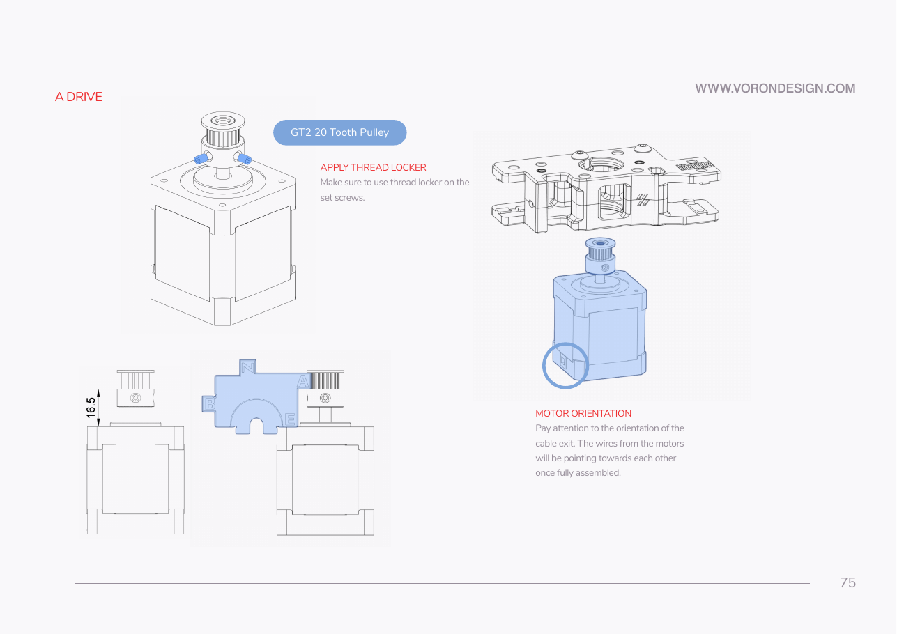
Step 04.24 — A drive: set the pulley on the A motor at 16.5 mm
Step 24 of 38 with a helper · Chapter 04 — A/B drive units and front idlers
Tap to enlarge
 Gather for this segment — steps 04.24–04.28 (~25 min)
Motion box
- GT2 20 T 6 mm pulley ×1
Fasteners, Tools & Misc box
- M3×30 SHCS ×3
Motor Kit box
- stepper motor, 0.9° A/B ×1
Tools and consumables
- printed
pulley_jig.stl· bin 00-jigs - caliper
- Loctite 243
- 1.5 mm hex key
- free end of the 6 mm belt reel, uncut
- masking tape
- marker
Already on the bench
- the pulley's two set screws
- the A motor with its pulley
Parts:
- stepper motor, 0.9° A/B ×1 · Motor Kit box
- GT2 20 T 6 mm pulley ×1 · Motion box
- printed
pulley_jig.stl· tool - caliper · tool
Do:
- Slide the pulley on hub first, teeth up.
- Stand the jig on the motor face beside the pulley, letters upright, A tab toward it.
- Drop it until its teeth underside is level with the A tab underside.
 Check
Caliper 16.5 mm, motor face to teeth underside, hub down. ~23 mm means pulley on tab, ~19.5 mm jig on feet.
 Helper Reads the caliper aloud while you slide the pulley along the shaft.
What you're looking at
Manual p.75: the A motor and its 20T 6 mm-wide GT2 pulley, set with the printed jig. The pulley height puts the belt in the same plane as the A idler's bearing channel; the underside of the jig's A tab repeats it without a caliper.
Jig misuse
the plate stands beside the pulley, never over the boss. Its two feet hang past the motor face; stood on the feet every height reads 3 mm high. Without the jig, set 16.5 mm with a caliper.
Caution
Rev D+ / LDO: the two A/B motors are 0.9° (LDO-42STH48-2004MAH(VRN)); the four Z motors are 1.8° and look identical. Read the label: -2004MAH = A/B (0.9°), -2004AC = Z (1.8°). Take an A/B motor, not a spare Z motor. This is why the LDO config carries full_steps_per_rotation: 400 in [stepper_x] and [stepper_y], set in Ch 12. src
Source: Voron manual p.75 · LDO Klipper config leviathan-printer-rev-d-sbv2.cfg · LDO 350 Rev D BOM · Video: Part 3 @1:11:48