Chapter 08 — Toolhead: Stealthburner, Clockwork 2, Revo HF, Nitehawk-SB V2
Start the chapter · Resume · Read the whole chapter on one page
Before — end of Ch 07: A and B belts closed
After — end of Ch 08: toolhead on the carriage
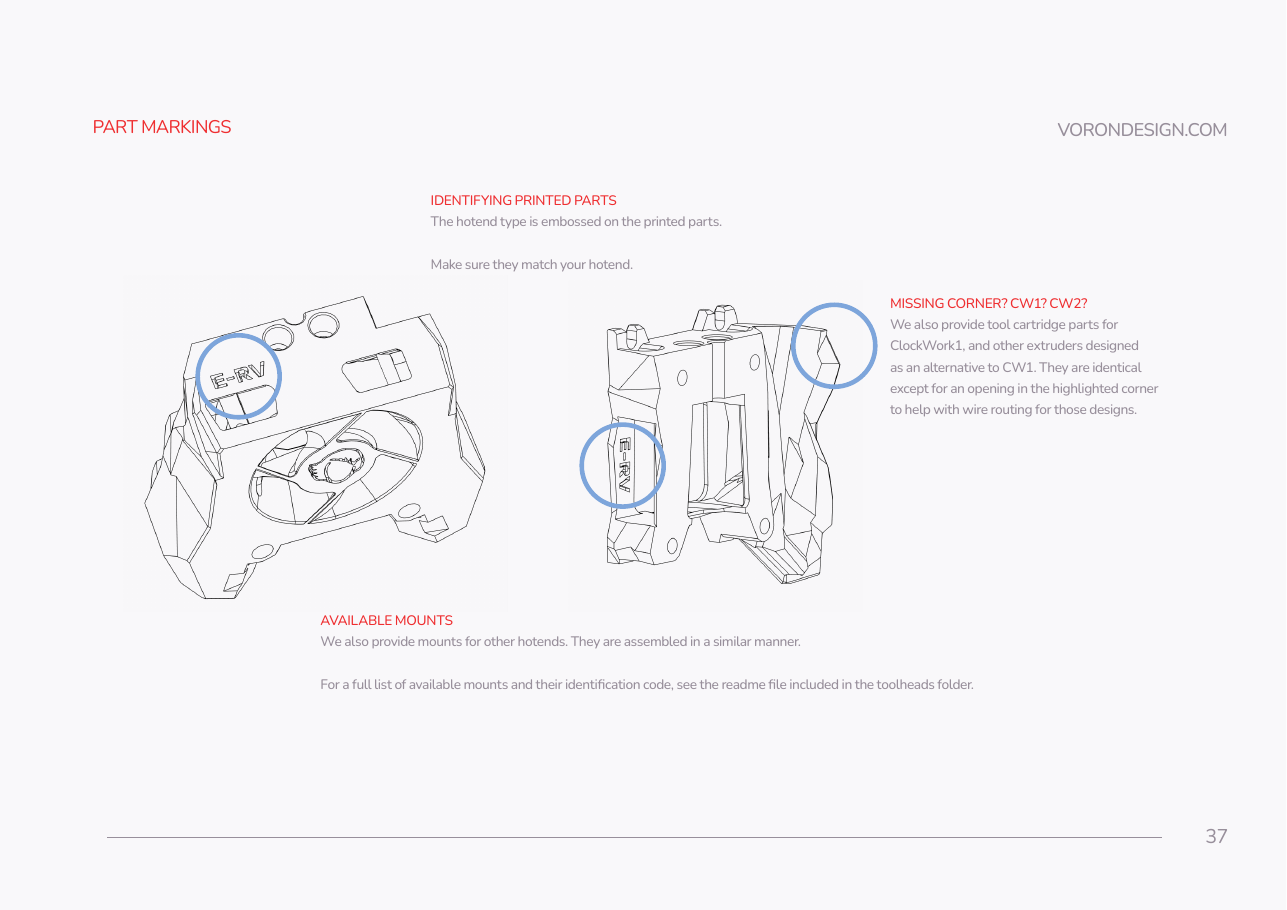 Step 08.1Sort the printed parts and confirm the hotend codewith a helper
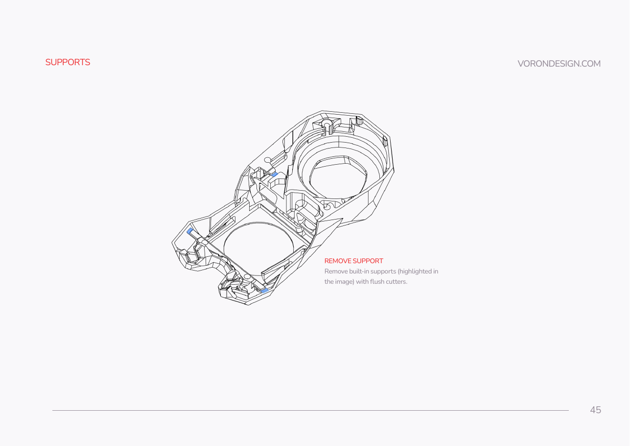 Step 08.2Snap the built-in supports out of the Stealthburner body
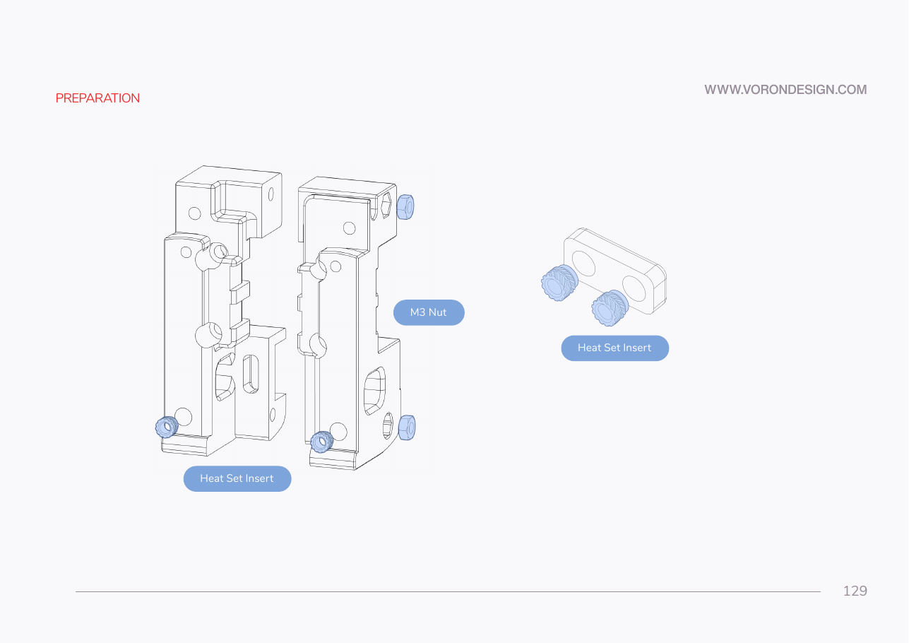
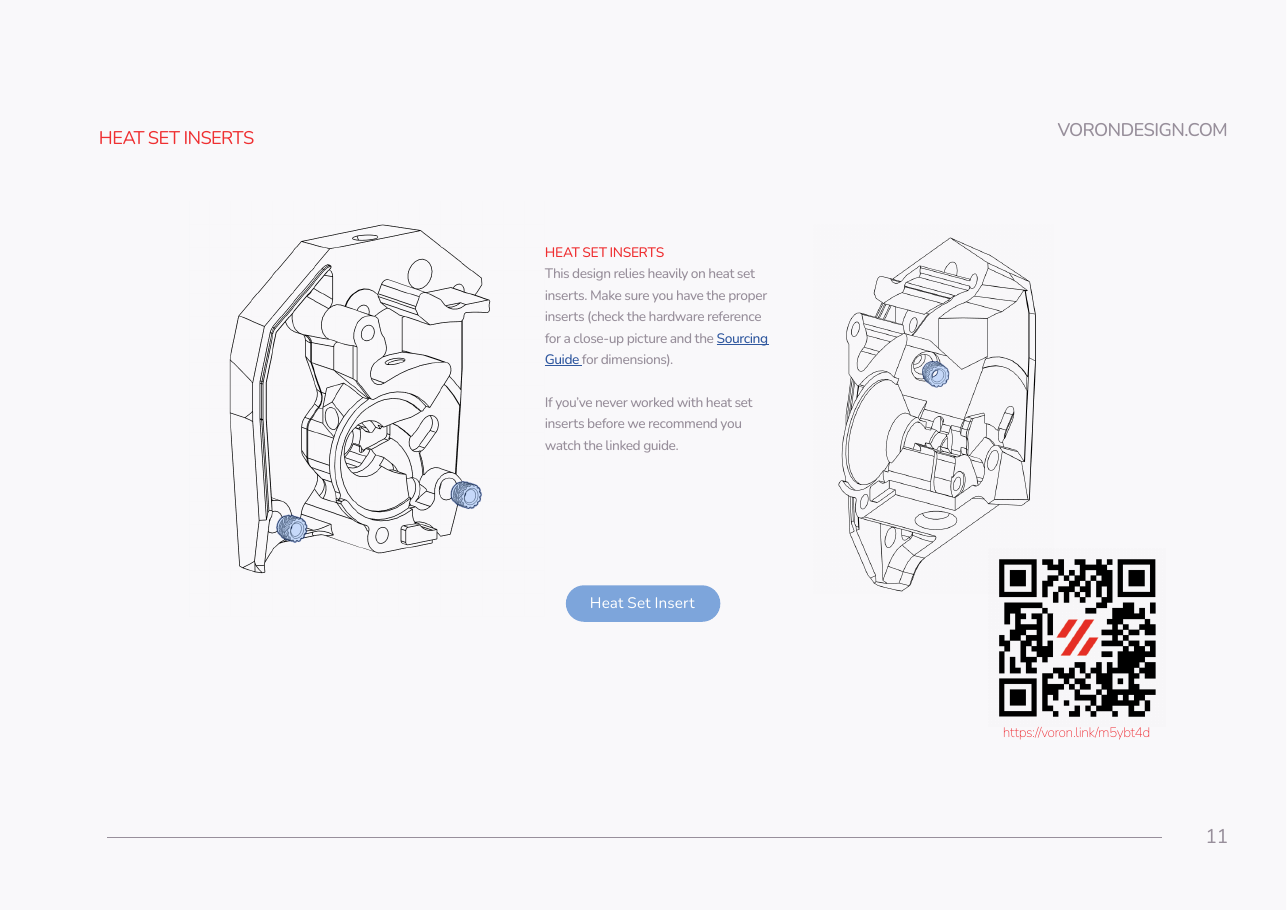 Step 08.3Inserts: Clockwork 2 main body
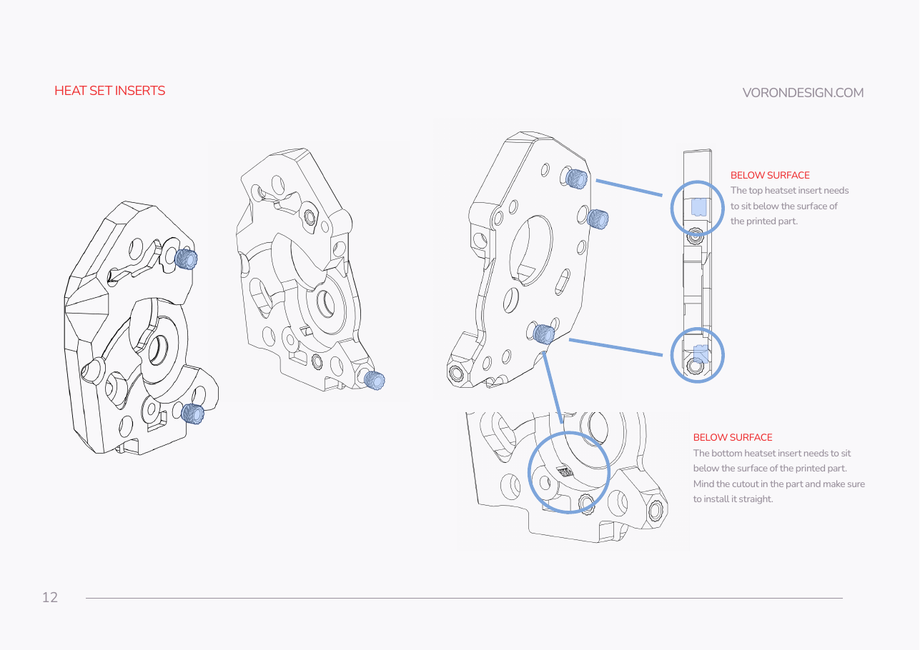 Step 08.4Inserts: Clockwork 2 motor plate
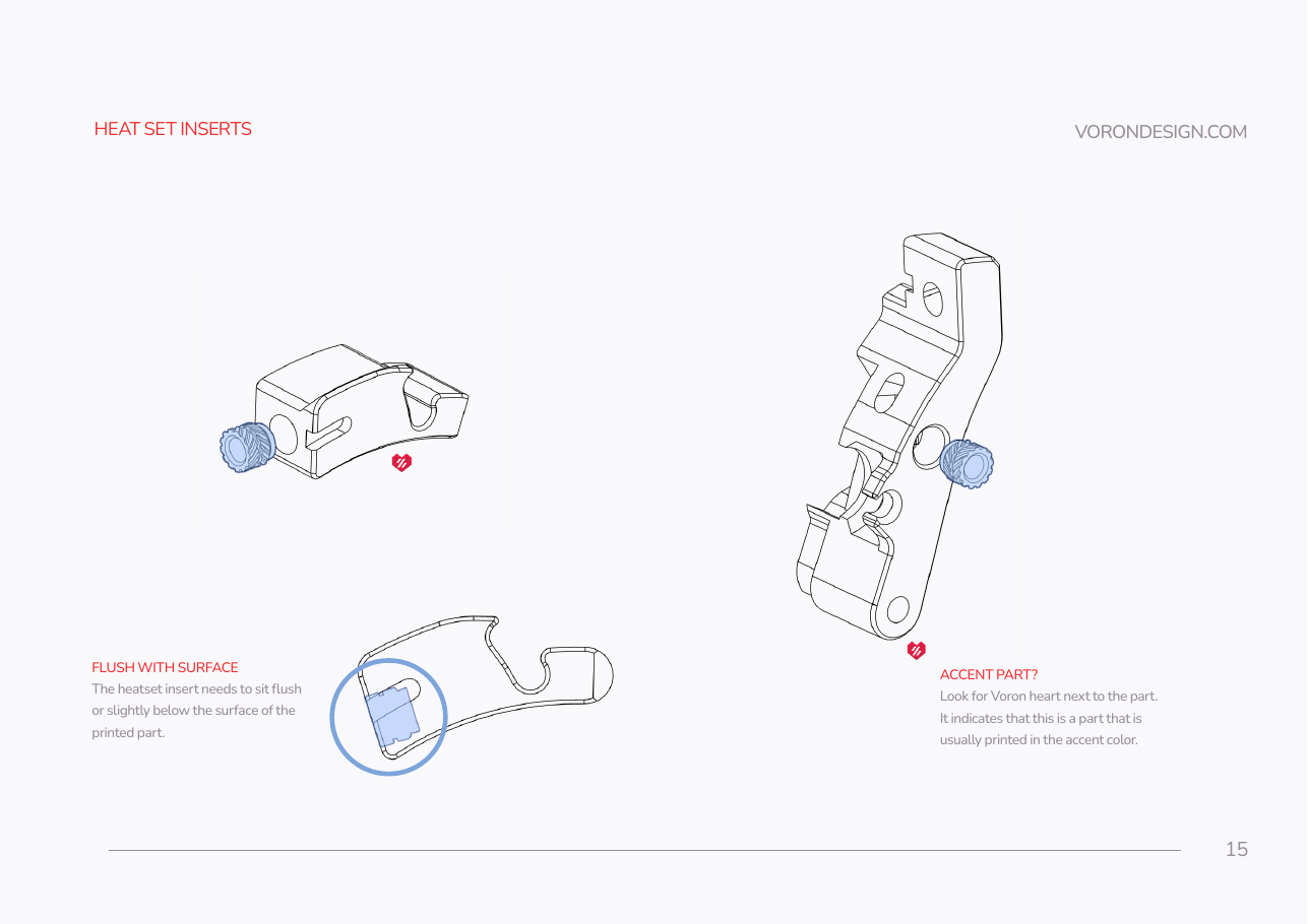 Step 08.5Inserts: latch shuttle and guidler arm (flush, not below)
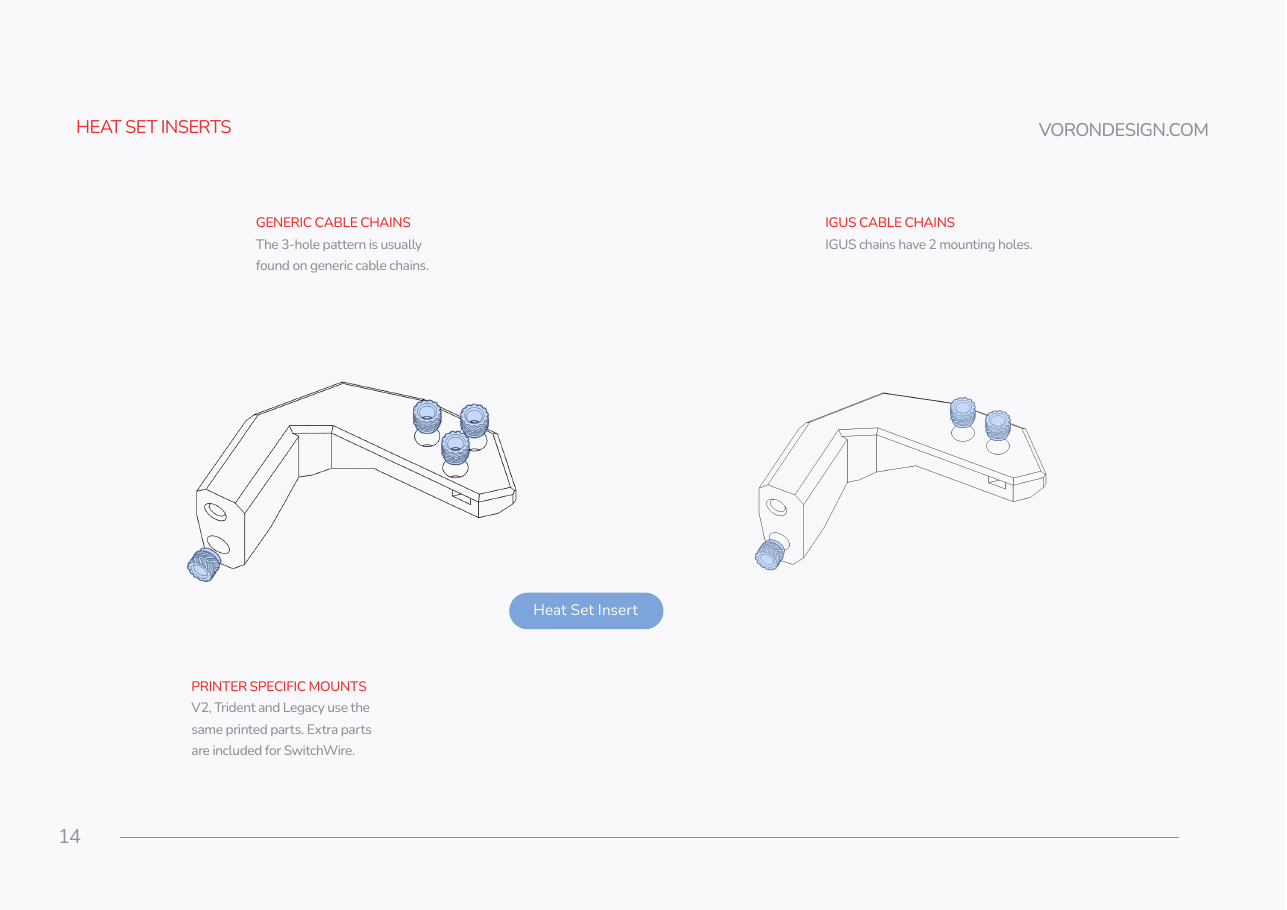 Step 08.6Inserts: CW2 chain anchor (Igus 2-hole pattern)
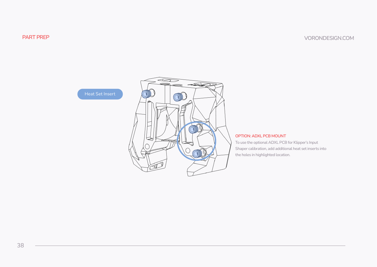 Step 08.7Inserts: rear printhead half — and the two you skip
 Step 08.8Confirm the X carriage is ready to receive a toolhead
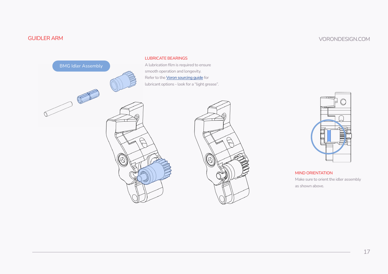 Step 08.9Build the BMG idler assembly and grease it
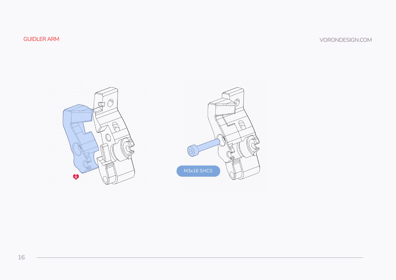 Step 08.10Close the guidler arm
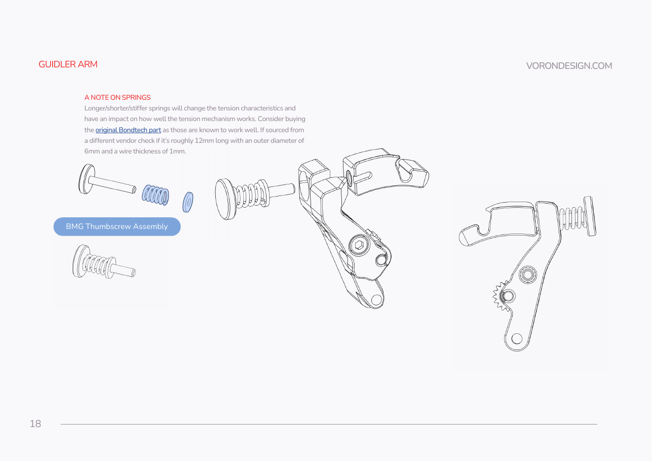 Step 08.11Fit the latch shuttle and the BMG thumbscrew assembly
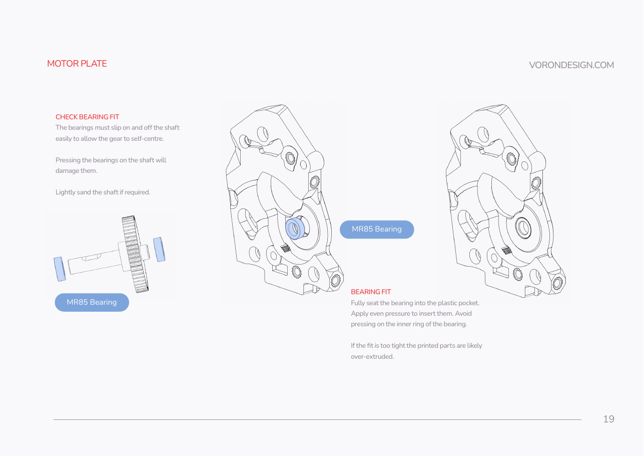 Step 08.12Seat the first MR85 in the motor plate
Step 08.13Check the drive shaft slides through both bearingswith a helper
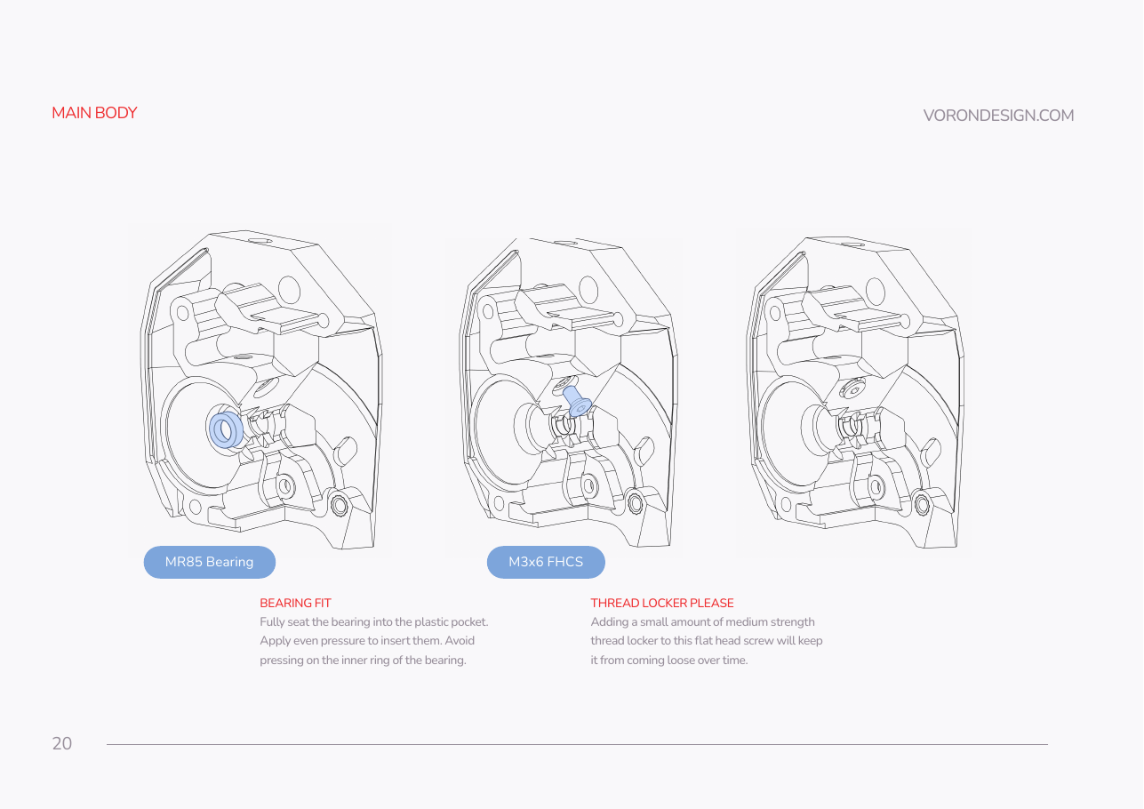 Step 08.14Seat the second MR85 in the main body and lock it
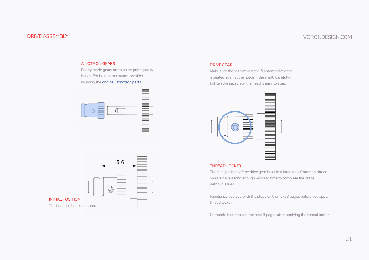 Step 08.15Set the drive gear at its initial position and threadlock it
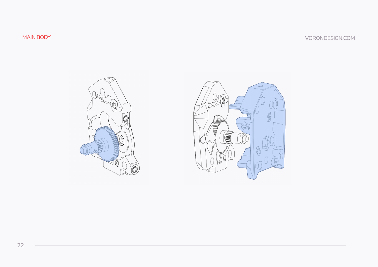 Step 08.16Drop the drive assembly into the main body
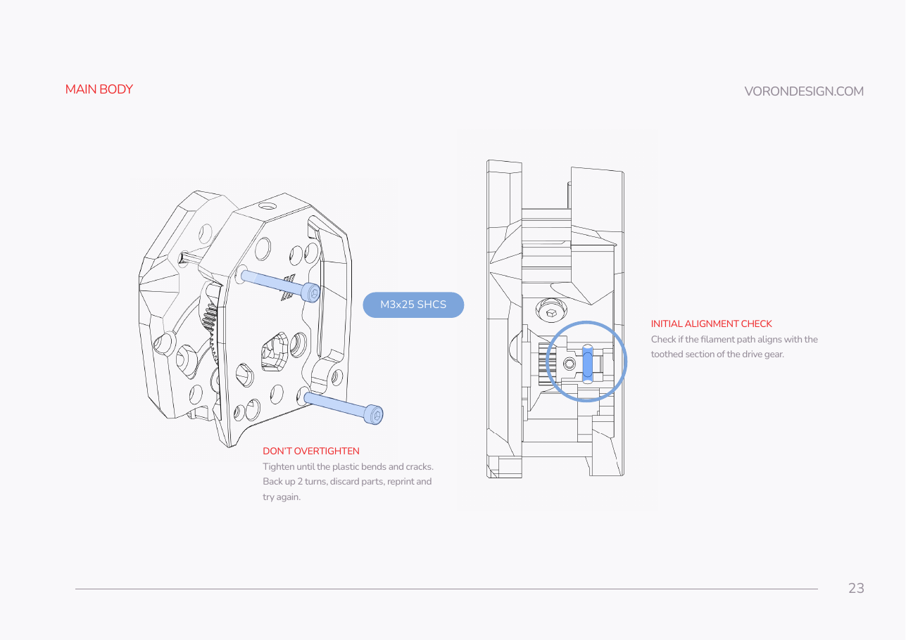 Step 08.17Close the extruder with the motor plate
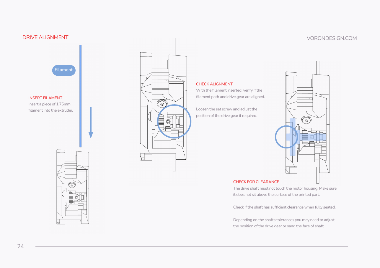 Step 08.18Verify drive-gear alignment with real filamentwith a helper
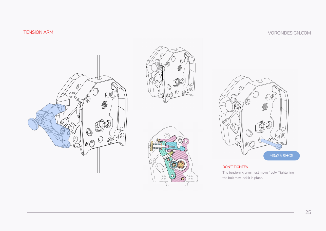 Step 08.19Hang the tension arm — and leave it loose
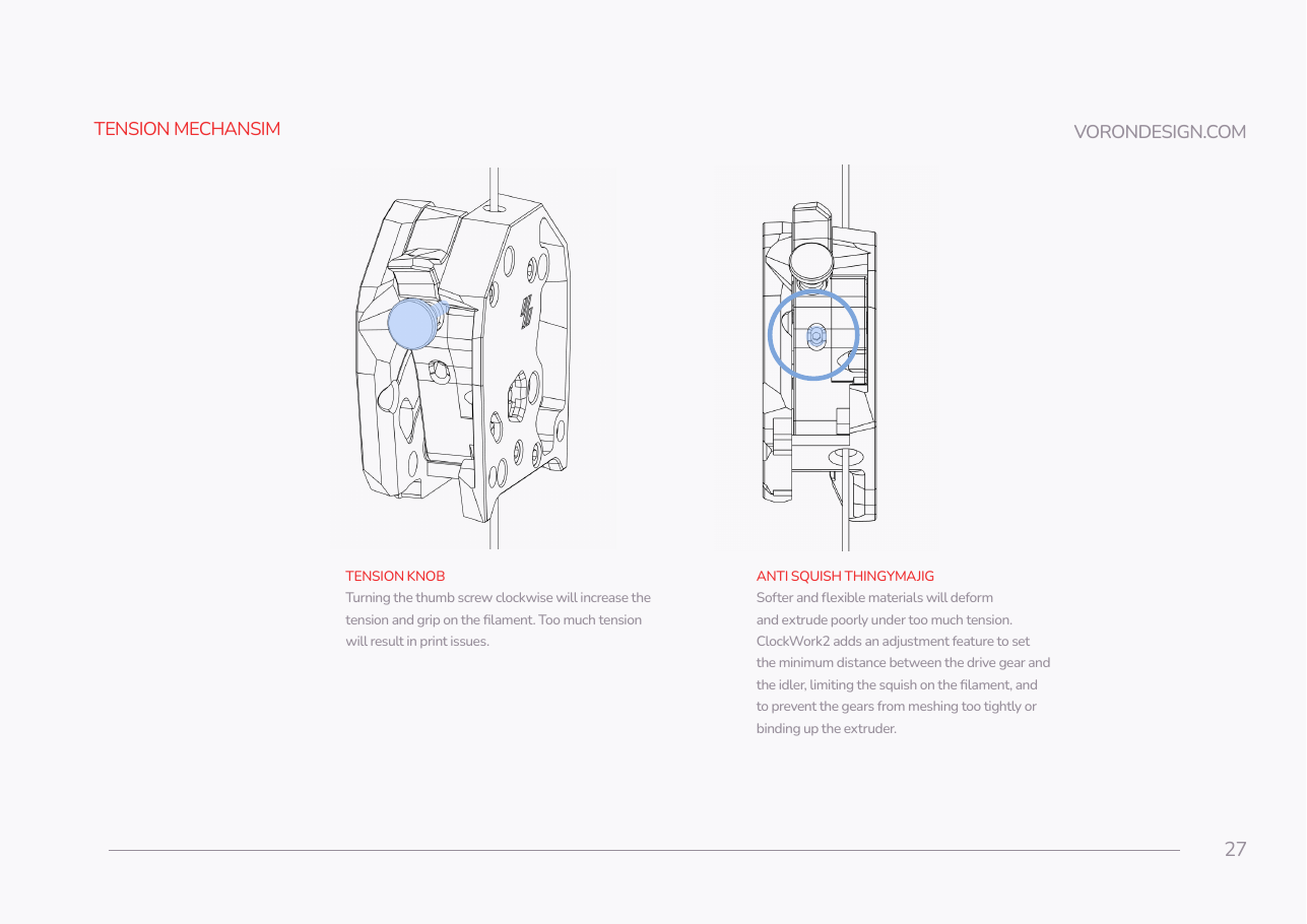 Step 08.21Set the tension and the anti-squish stop
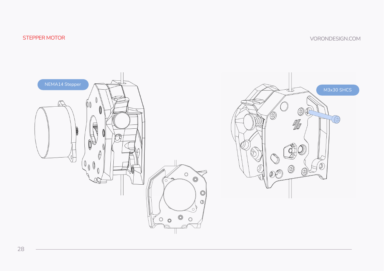 Step 08.22Fit the pancake stepper, first bolt
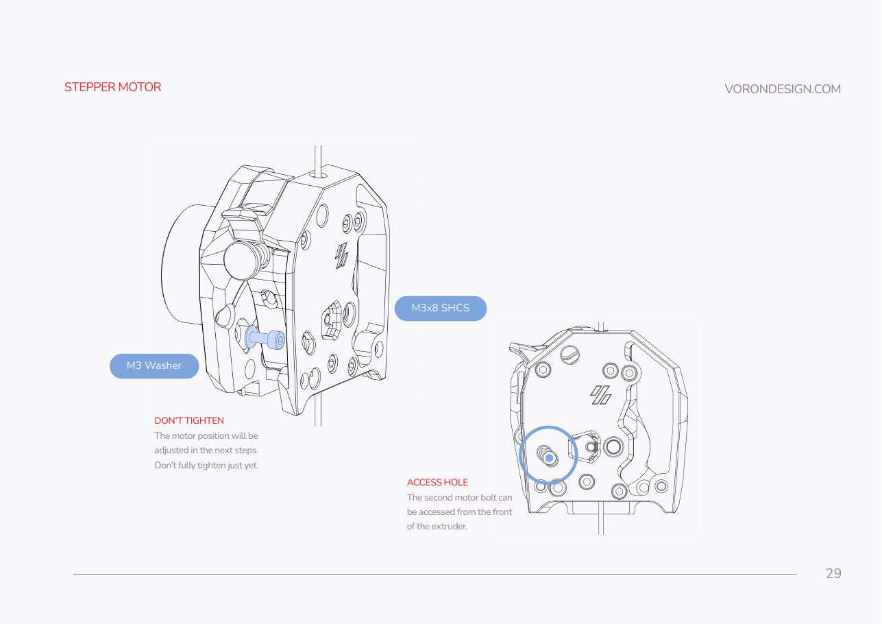 Step 08.23Fit the second motor bolt through the front access hole
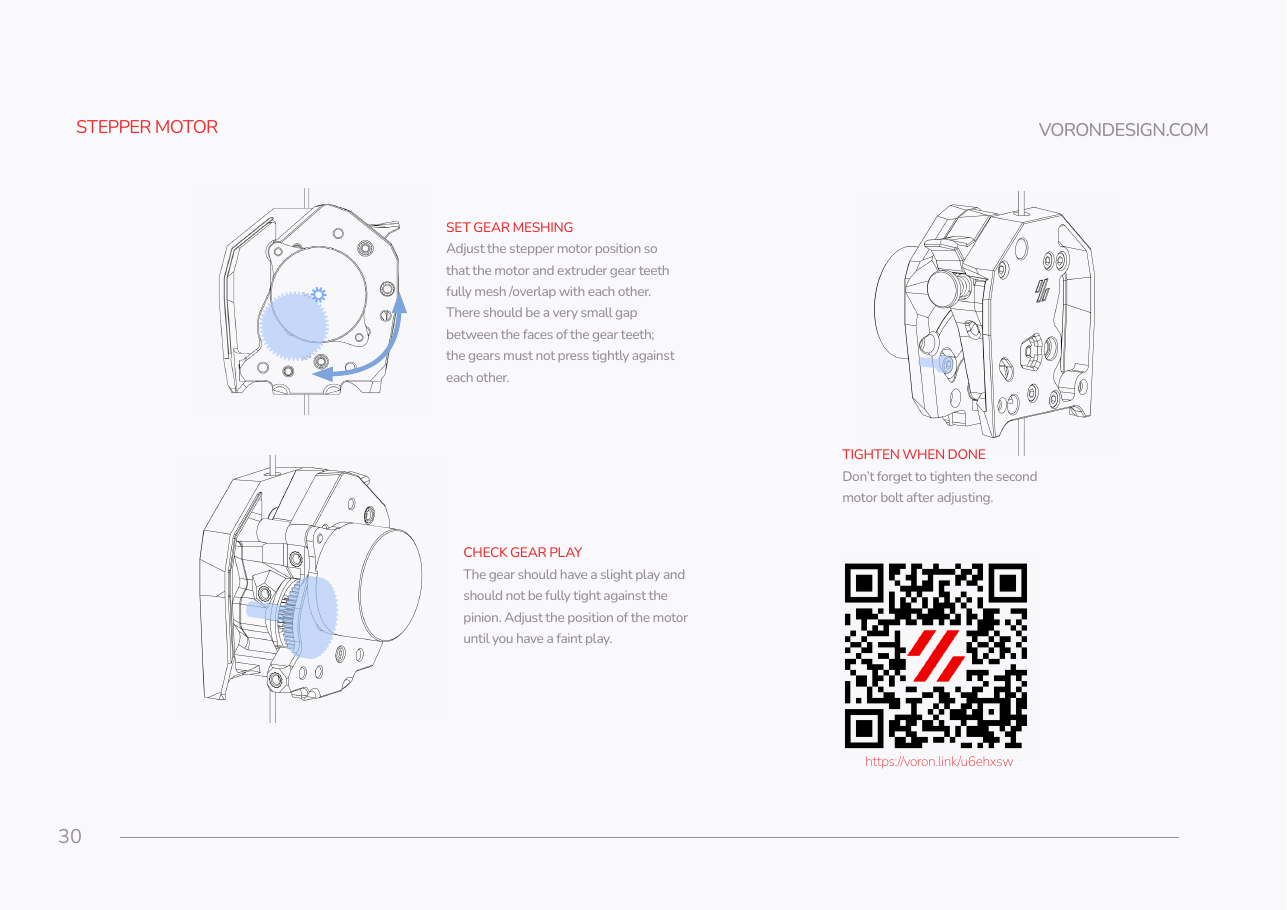 Step 08.24Set the gear mesh, then tighten both motor bolts
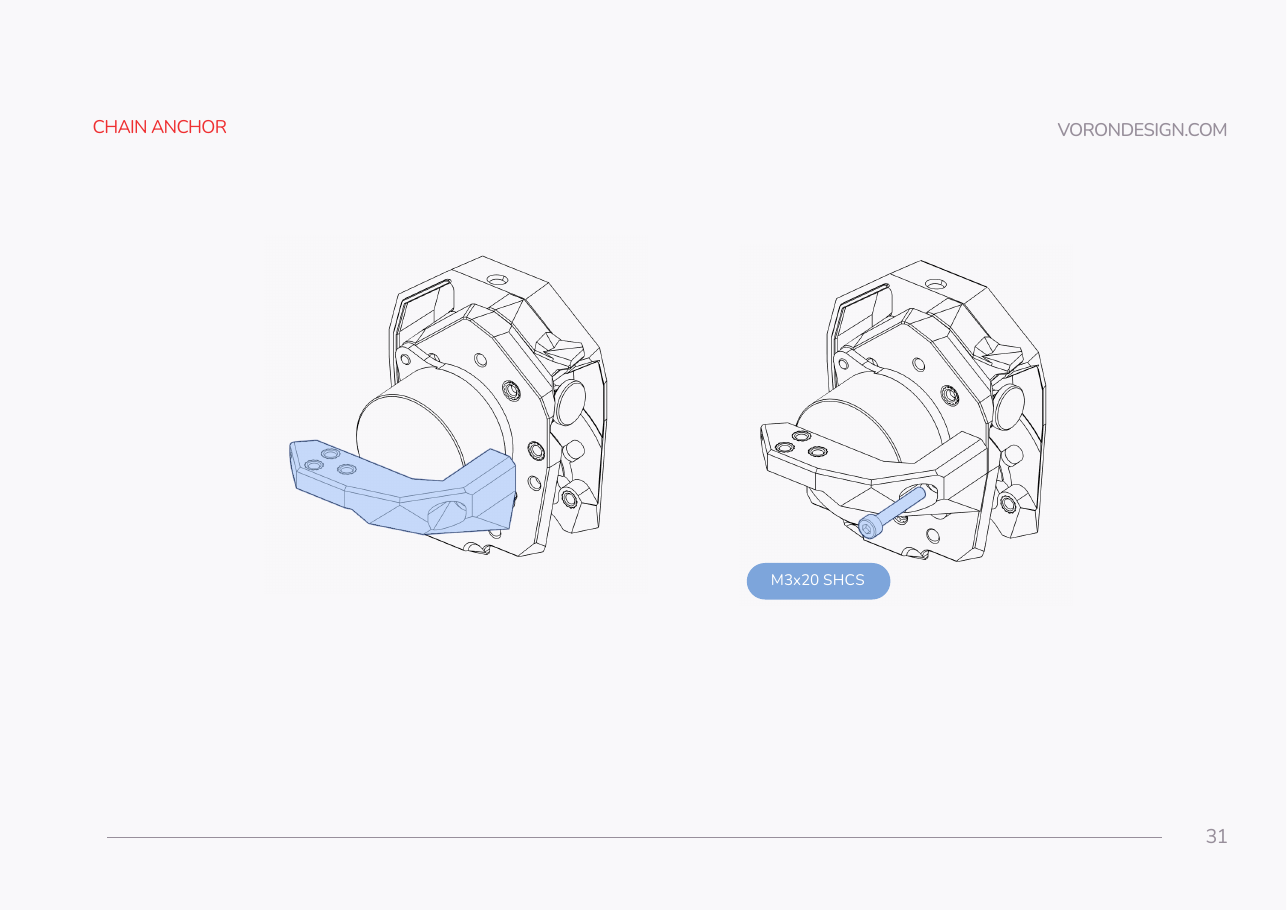 Step 08.25Fit the LDO tilted chain anchor
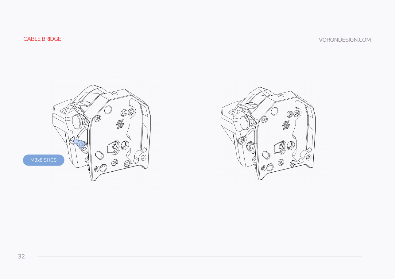 Step 08.26Fit the cable-bridge bolt
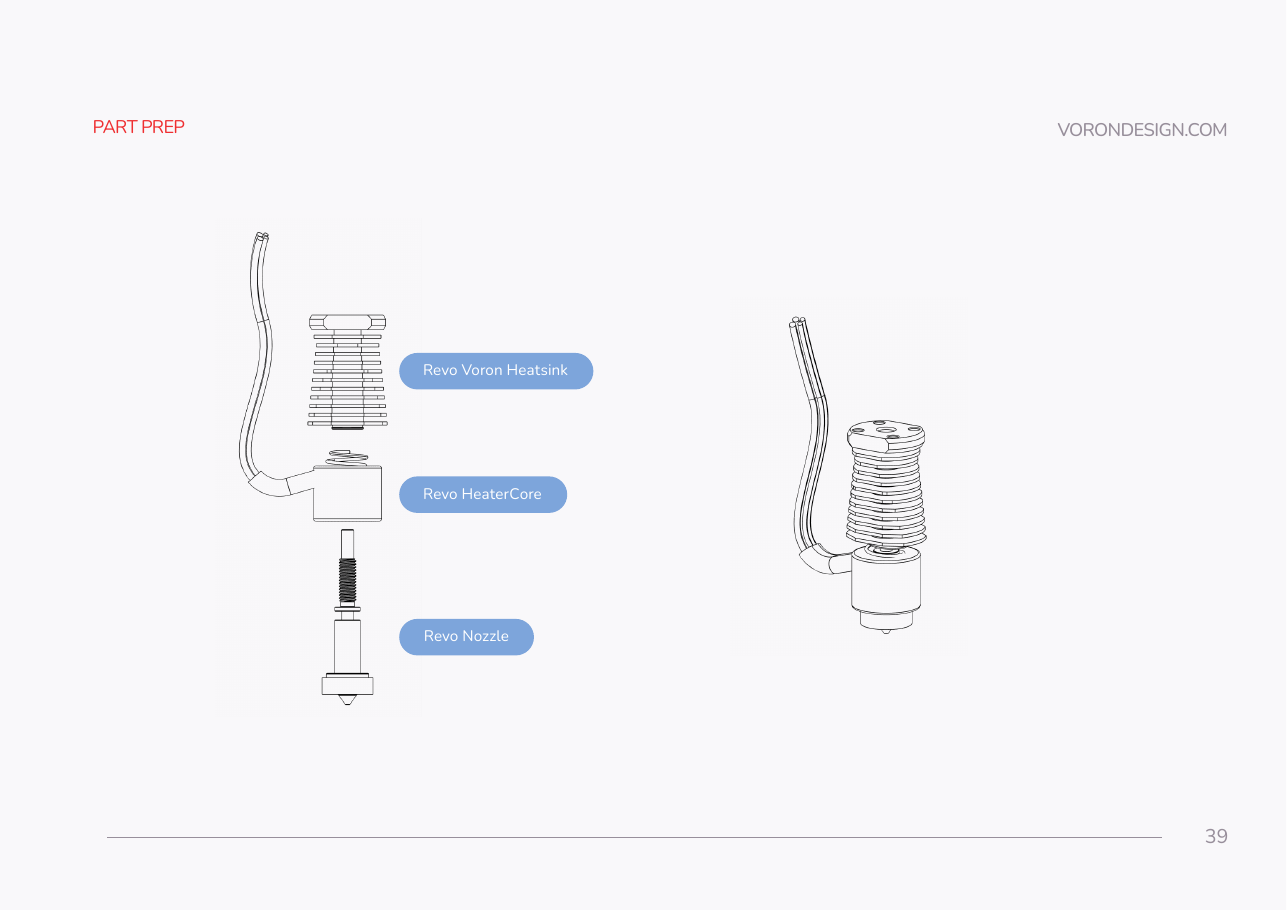 Step 08.27Assemble the Revo HF hotend
Step 08.28Seat the hotend in the rear printhead half
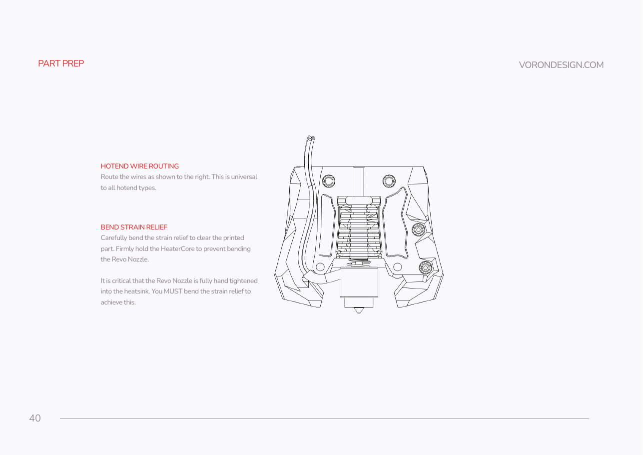 Step 08.29Route the wires and bend the strain relief so the nozzle can seat fully
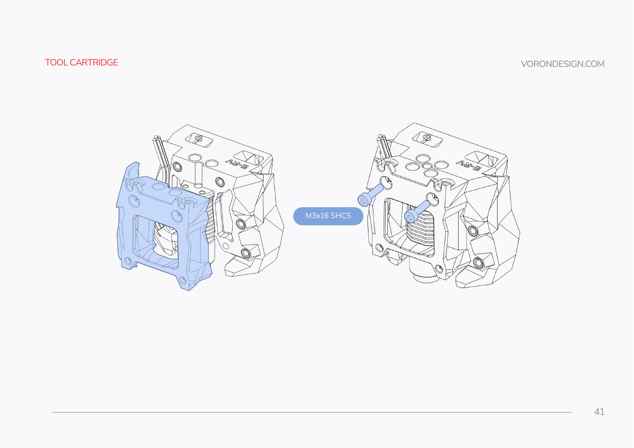 Step 08.30Close the tool cartridge
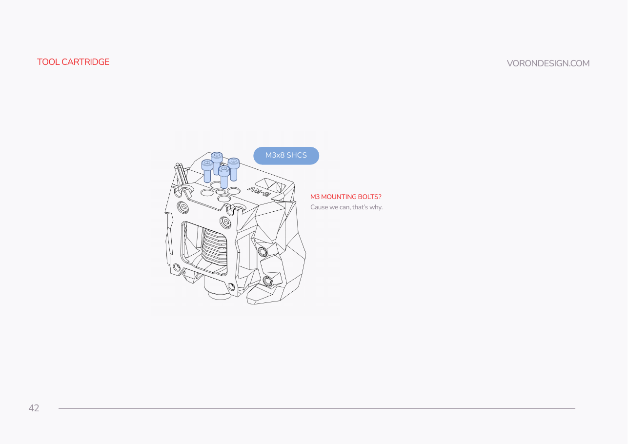 Step 08.31Fit the four tool-cartridge mounting boltswith a helper
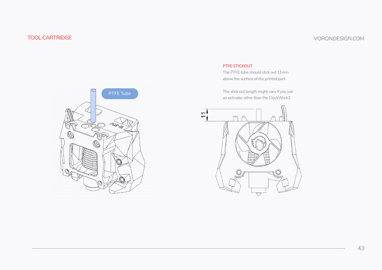 Step 08.32Cut and fit the PTFE to 11 mm stickout
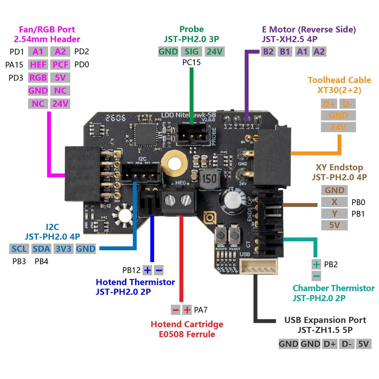 Step 08.33Terminate the hotend leads for the Nitehawk V2
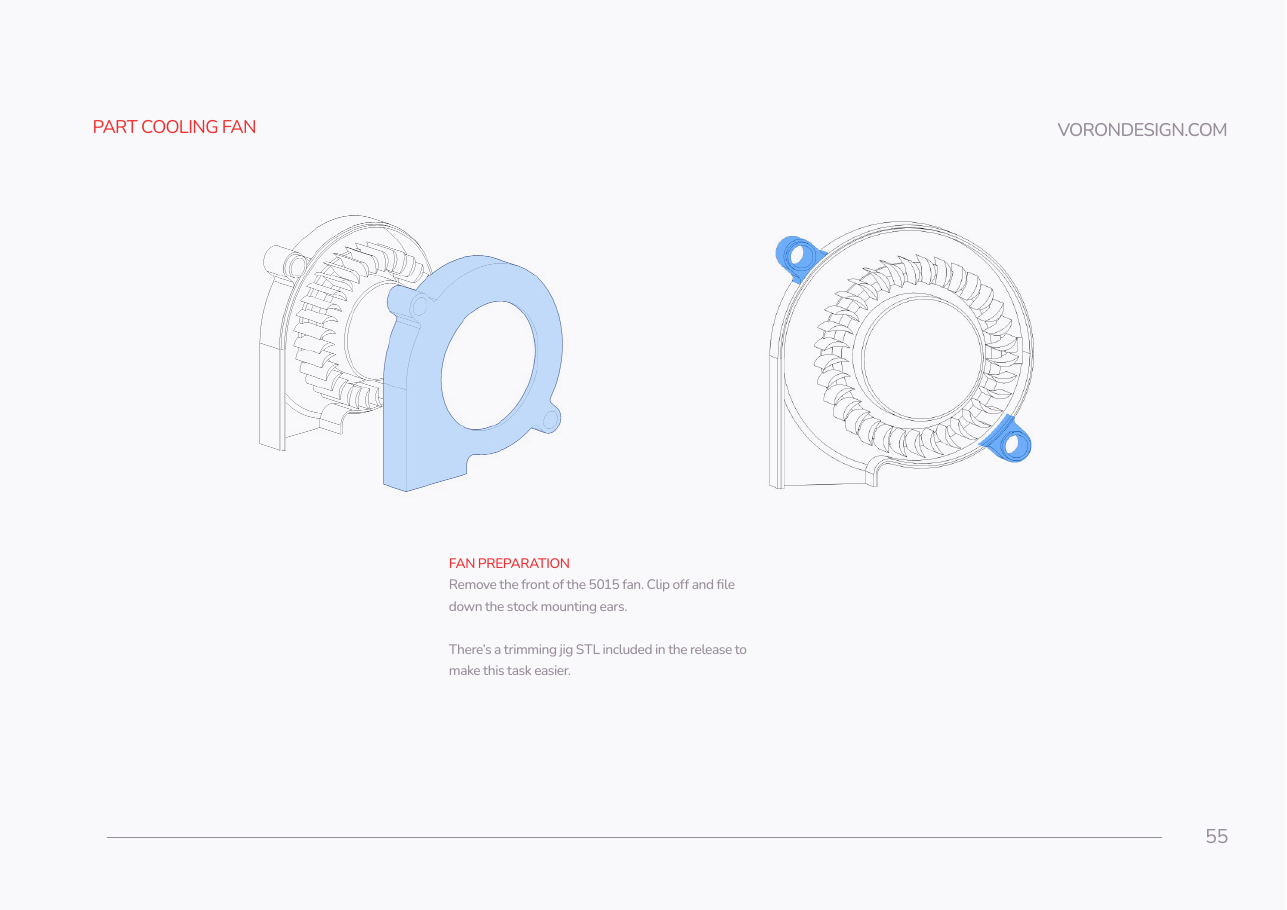 Step 08.34Prepare the 5015 part-cooling blower
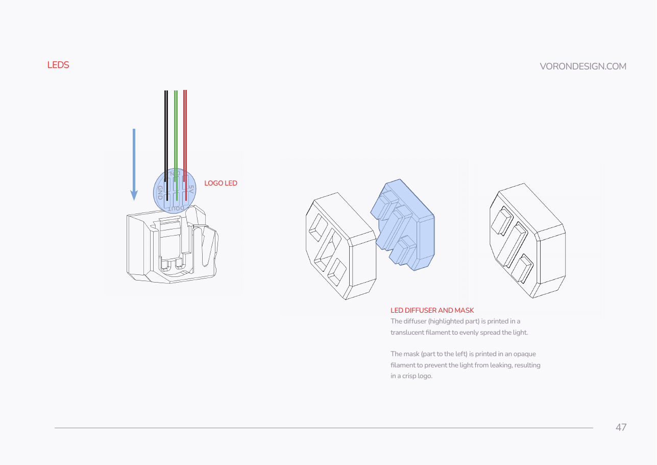 Step 08.35Build the logo LED into its carrier
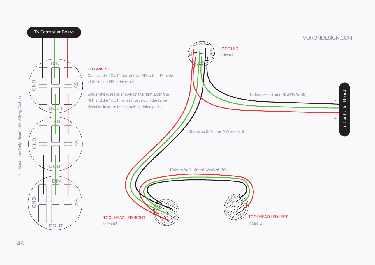 Step 08.36Wire the three-LED chain
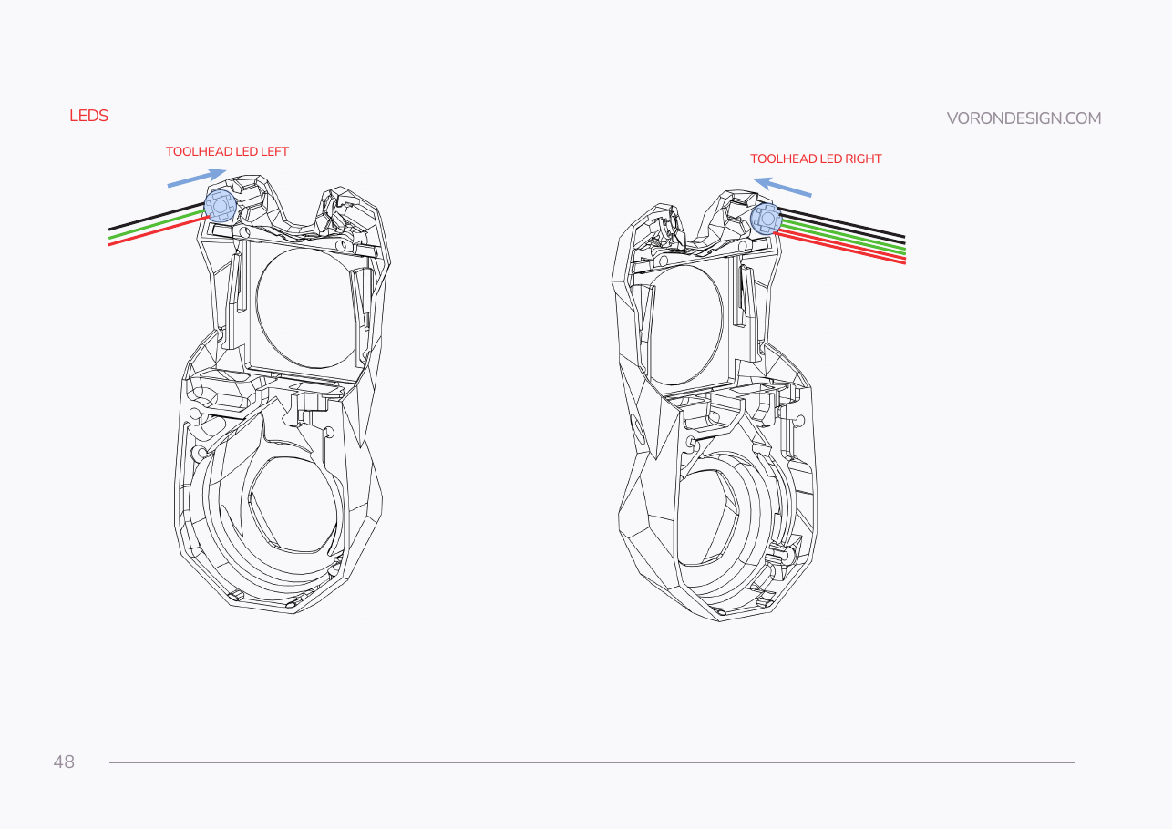 Step 08.37Seat the two toolhead LEDs
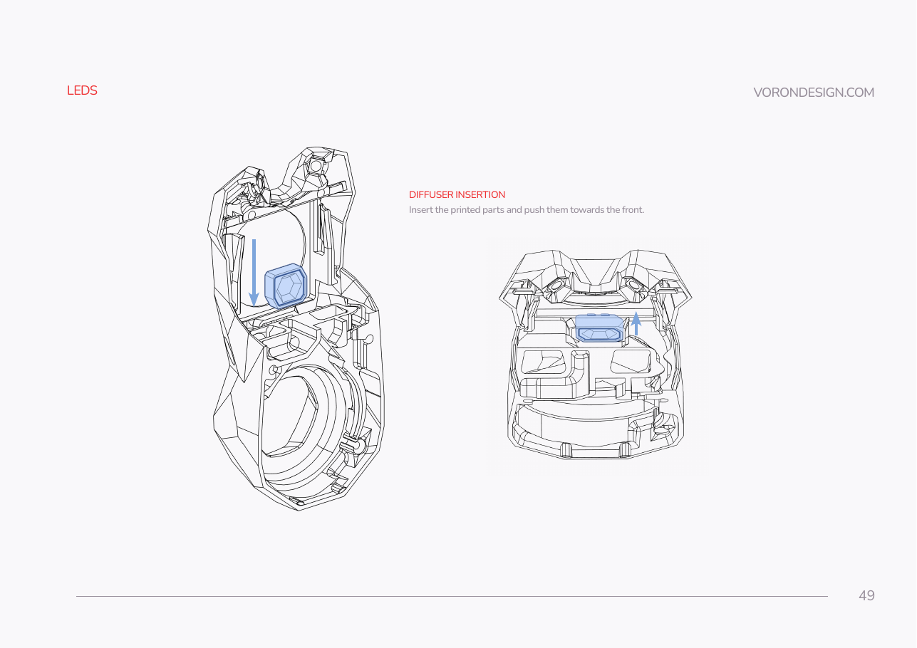 Step 08.38Insert the LED diffusers and push them forward
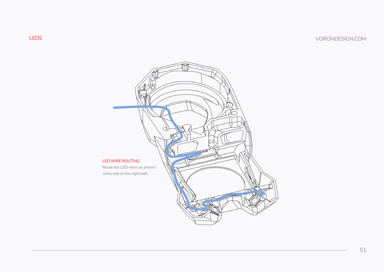 Step 08.39Route the LED wires out of the body
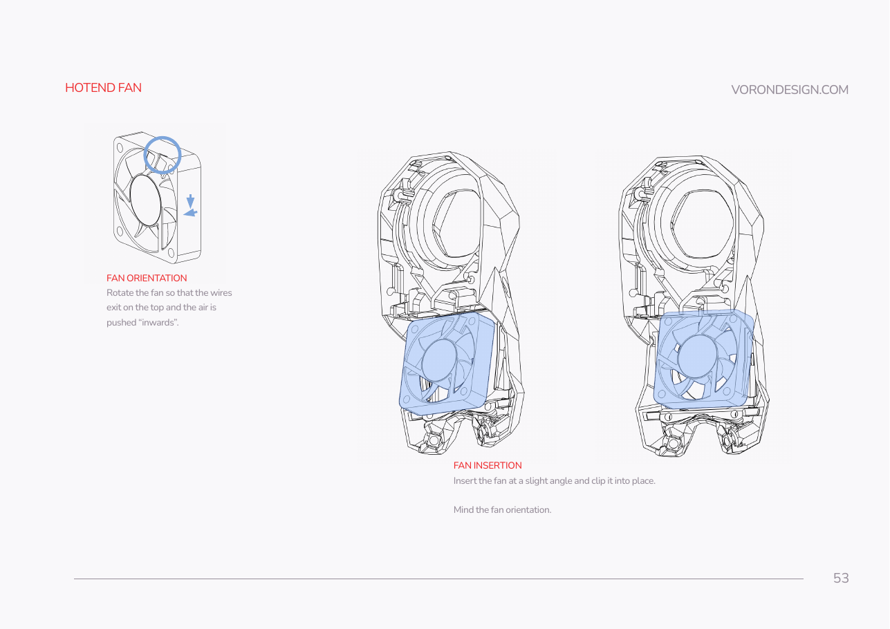 Step 08.40Clip in the hotend fan, correct way roundwith a helper
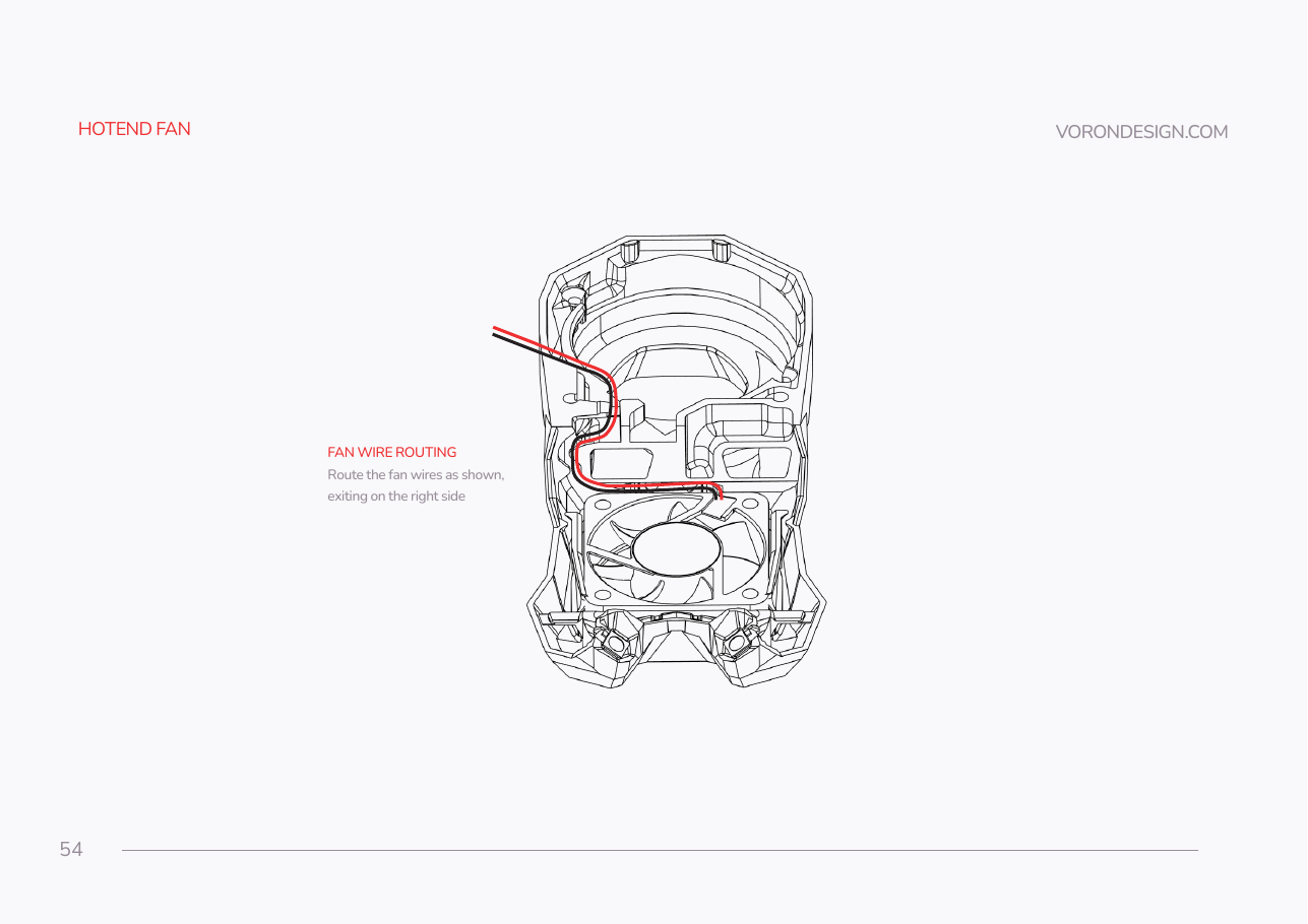 Step 08.41Route the hotend fan wires
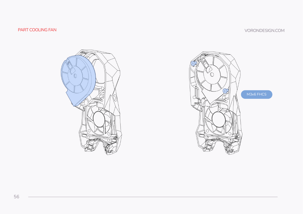 Step 08.42Fit the part-cooling blower
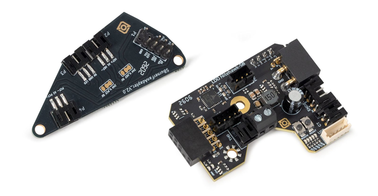 Step 08.43Bolt the Nitehawk-SB V2 to the Clockwork 2
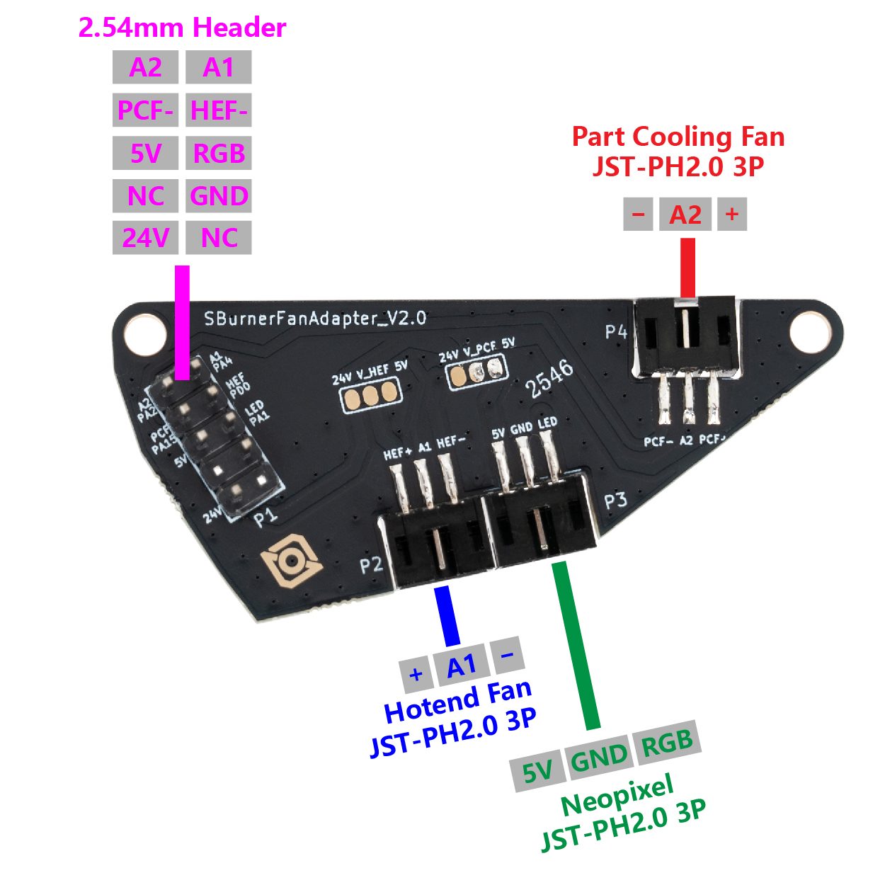 Step 08.44Mount the fan adapter PCB on the back of the 5015
Step 08.45Check the fan-voltage solder jumpers before anything is poweredwith a helper
Step 08.46Plug the fans and the LED chain into the adapter
Step 08.47Hotend heater into the screw terminal
Step 08.48Hotend thermistor into TH0with a helper
Step 08.49Extruder motor into E MOTOR
Step 08.51Chamber thermistor into CT, then close the LDO cable cover
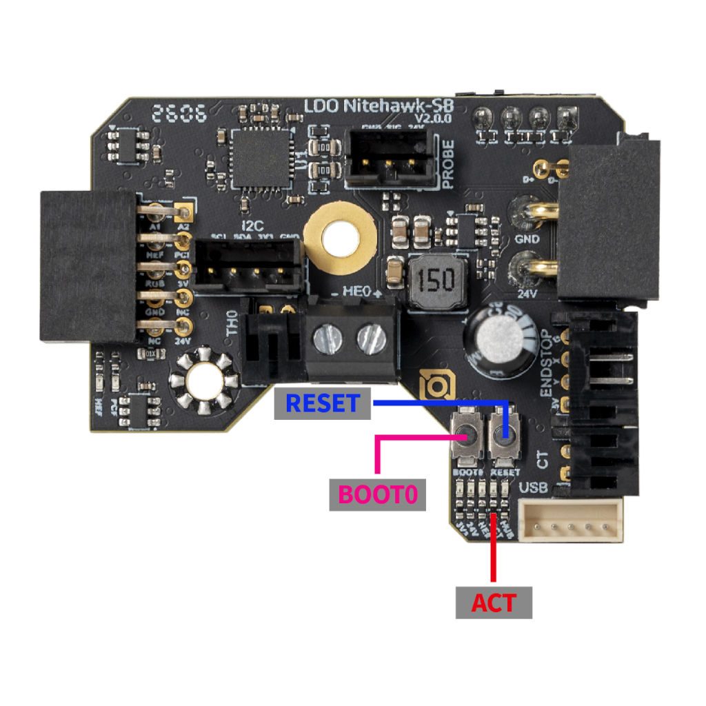 Step 08.52Account for the ports you are not usingwith a helper
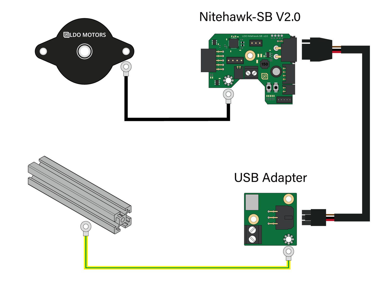 Step 08.53Land the ground wire's motor end on the extruder motor
Step 08.54Confirm the probe decision and bag the Klicky set
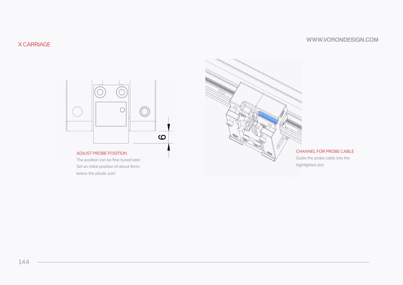 Step 08.55Confirm the inductive probe fitted in Ch 07with a helper
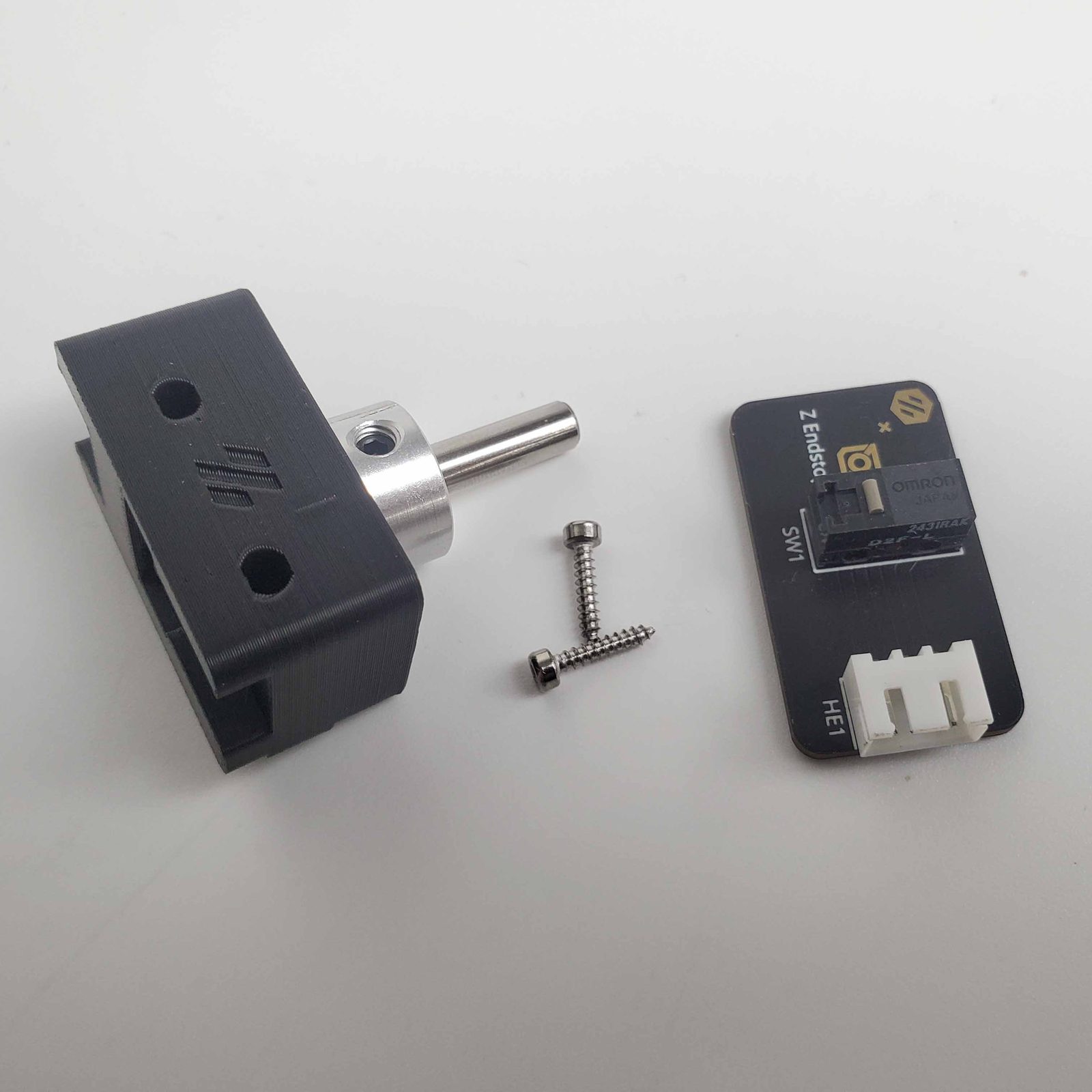 Step 08.56The LDO nozzle probe is built in Ch 09 — not here
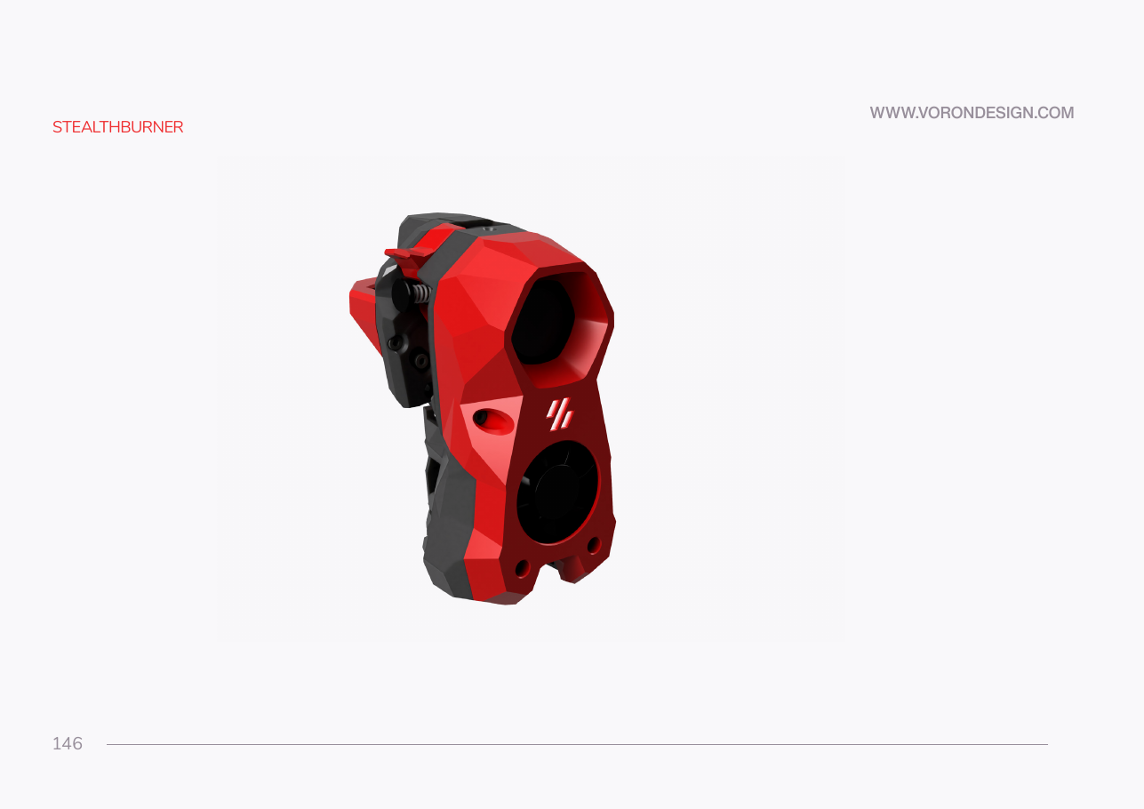 Step 08.57Read the handoff page and get help for the lift
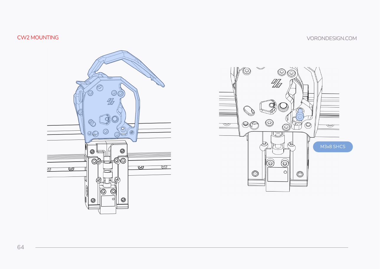 Step 08.58Hang the Clockwork 2 on the carriage, first boltwith a helper
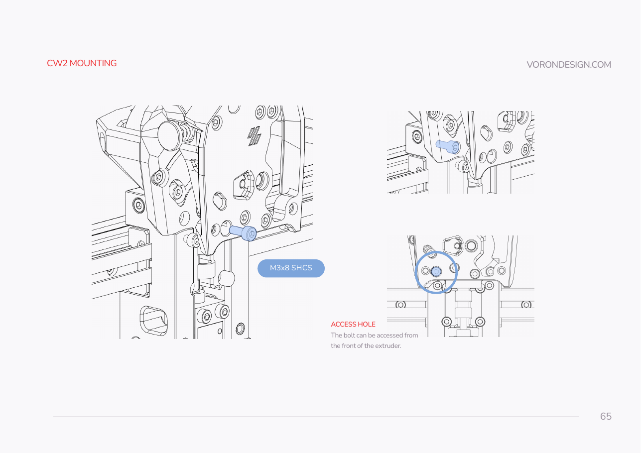 Step 08.59Second CW2 bolt, through the front access hole
Step 08.60Plug in the toolhead cable
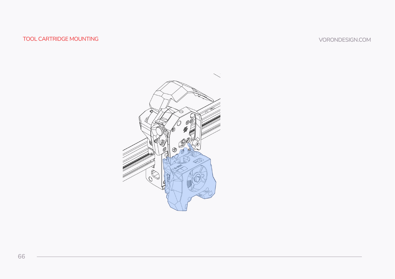 Step 08.61Slide the tool cartridge into place
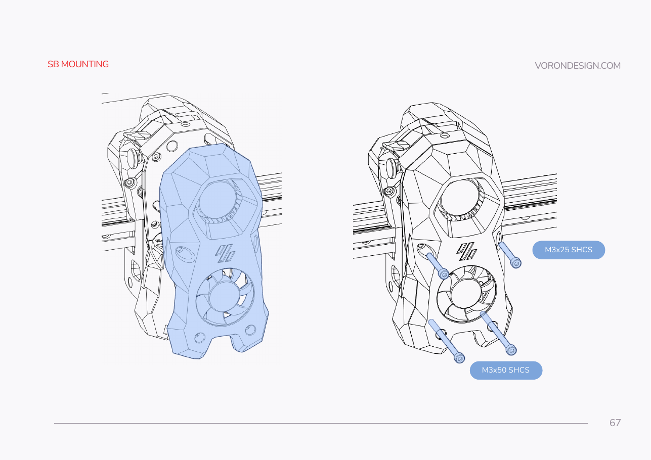 Step 08.62Fit the Stealthburner body and mate the board-to-board header
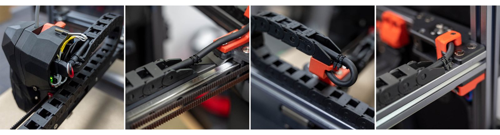 Step 08.63Park the umbilical on the chain anchor — chain ties are Ch 10
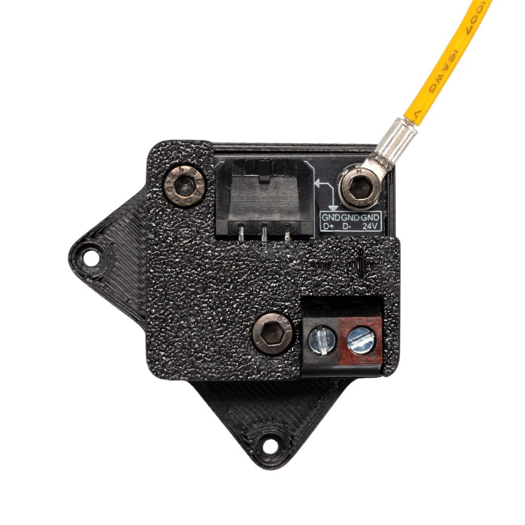 Step 08.64Set the USB adapter aside with the right coverwith a helper
 Step 08.65Return to the printer manual
Checkpoint 08 — bench test before anything is poweredTick before moving on
Gather per session — what to lay out before each bench segment.
- Steps 08.1–08.8 · ~35 min — Fasteners, Tools & Misc box: heat-set insert, M3×5×4 ×18 · Printed parts:
main_body.stl×1 (bin 08-CW2);motor_plate.stl×1 (bin 08-CW2);[a]_latch_shuttle×1 (bin 08-CW2);[a]_guidler_a×1 (bin 08-CW2);[a]_stealthburner_main_body×1 (bin 08-SB);stealthburner_printhead_revo_voron_rear_cw2×1 (bin 08-SB) · Set out for later steps: all B02 and B06 toolhead prints; the tworevo_voronprinthead halves; CW2 Chain Anchor Tilted ×1 · Already on the bench: the X carriage on the gantry - Steps 08.9–08.18 · ~30 min — Motion box: Bondtech IDGA gear set ×1; Thumb Screw Kit ×1; MR85 bearing ×2 · Fasteners, Tools & Misc box: M3×16 SHCS ×1; M3×6 FHCS ×1; M3×25 SHCS ×2 · Printed parts:
[a]_guidler_a×1 (bin 08-CW2);[a]_guidler_b×1 (bin 08-CW2);[a]_latch_shuttle×1 (bin 08-CW2) · Tools and consumables: light grease, Super Lube; sandpaper, fine; medium-strength threadlocker; caliper; 1.75 mm filament, a 100 mm offcut · Already on the bench: the greased idler assembly; the motor plate with its inserts; the drive shaft from the IDGA set; the MR85 in the motor plate; the CW2 main body with its inserts; the drive assembly; the CW2 main body - Steps 08.19–08.26 · ~25 min — Electronics 2 box: CW2 Chain Anchor Tilted ×1 · Fasteners, Tools & Misc box: M3×25 SHCS ×2; M3×30 SHCS ×1; M3×8 SHCS ×2; M3 washer ×1; M3×20 SHCS ×1 · Motor Kit box: LDO-36STH20-1004AHG(VRN) NEMA14 pancake stepper ×1 · Printed parts:
[a]_latch×1 (bin 08-CW2) · Tools and consumables: 1.75 mm filament offcut · Already on the bench: the guidler assembly; the assembled extruder; the extruder assembly - Steps 08.27–08.32 · ~20 min — Fasteners, Tools & Misc box: M3×16 SHCS ×2; M3×8 SHCS ×4 · Other box: E3D Revo HF hotend, assembled ×1 · Printed parts:
stealthburner_printhead_revo_voron_front×1 (bin 08-SB) · Tools and consumables: PTFE tube, 4 mm OD, 2 mm ID, 10 cm; caliper; flush cutters · Already on the bench: the rear printhead half with its inserts; the Revo in the rear half - Steps 08.33–08.36 · ~25 min — Electronics 2 box: Stealthburner LED Diffuser, clear PETG ×1 · The LDO kit, no BOM row: logo LED, chain index 1 ×1; toolhead LED, chain index 2 and 3 ×2 · Printed parts:
[o]_stealthburner_LED_carrier×1 (bin 08-SB);[o]_stealthburner_LED_diffuser_mask×1 (bin 08-SB) · Tools and consumables: E0508 ferrule, only if re-terminating ×2; JST-PH2.0 2-pin housing and crimps, only if re-terminating; flush cutters; small flat file; 3-core 0.16 mm² wire, AWG26–30, 320 mm, only if not pre-soldered · Set out for later steps: 50×50×15 centrifugal fan, 24 V ×1 · Already on the bench: the Revo heater and thermistor leads; the logo LED in its carrier - Steps 08.37–08.42 · ~20 min — Fasteners, Tools & Misc box: M3×6 FHCS ×2 · Belts, Chains & Fans box: 40×40×10 axial fan, 24 V ×1; 50×50×15 centrifugal fan, trimmed ×1 · Already on the bench: the two toolhead LEDs on their chain; the Stealthburner main body; the logo LED stack, mask with diffuser and the LED carrier; the LED chain in the body; the hotend fan's leads
- Steps 08.43–08.46 · ~20 min — Electronics 2 box: Nitehawk-SB V2 ×1; CW2 PCB Spacer (supplied printed) ×1; Stealthburner Fan Adapter PCB (SBurnerFanAdapter_V2.0) ×1 · Fasteners, Tools & Misc box: M3×8 SHCS ×2; M3×10 FHCS ×2 · Tools and consumables: magnifier; multimeter · Already on the bench: the fan adapter PCB; the hotend fan, 5015 and LED chain leads
- Steps 08.47–08.53 · ~25 min — Fasteners, Tools & Misc box: M3×6 captive screw ×1 · The LDO kit, no BOM row: chamber thermistor, pre-terminated ×1; grounding cable, toolboard to extruder motor ×1; M3 screw, motor end of the grounding cable ×1 · Printed parts:
cw2_captive_pcb_cover.stl×1 (bin 08-CW2) · Tools and consumables: 2.5 mm slot-head screwdriver; multimeter · Already on the bench: the Revo heater leads; the pancake stepper lead; the inductive probe's pre-terminated lead - Steps 08.54–08.56 · ~10 min — nothing to lay out
- Steps 08.57–08.65 · ~35 min — Cable Kit 2.4-350 box: toolhead cable, USB and 24 V, XT30(2+2) ×1 · Electronics 2 box: USB Adapter PCB ×1; NH Adapter Mount ×1 · Fasteners, Tools & Misc box: M3×8 SHCS ×2; M3×25 SHCS ×2; M3×50 SHCS ×2 · The kit, no 350 BOM row: M3×10 SHCS ×3 · Printed parts:
usb_adapter_mount_partial_cover.stl(Nitehawk-SB-V2 repo) ×1 (bin 08-CW2) · Tools and consumables: zip tie, 3×150 mm ×1 · Already on the bench: the CW2 assembly with its toolboard; the tool cartridge with its four M3×8 studs; the Stealthburner body with LEDs, fans and fan adapter; the toolhead cable