Chapter 07 — A/B belts and tensioning
Start the chapter · Resume · Read the whole chapter on one page
Before — end of Ch 06: gantry on the Z joints, Z belts run
After — end of Ch 07: A and B belts closed
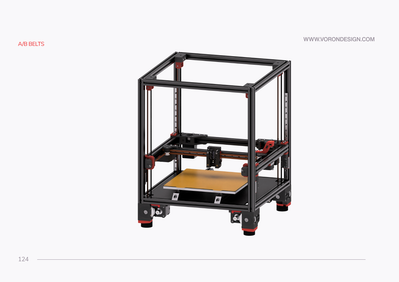 Step 07.1Confirm the gate before you start
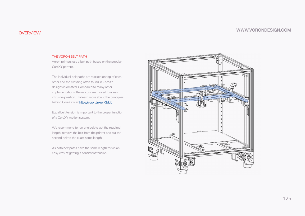 Step 07.2Learn the rule that governs this chapter
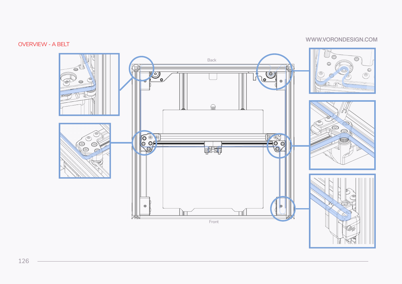 Step 07.3Trace the A belt path
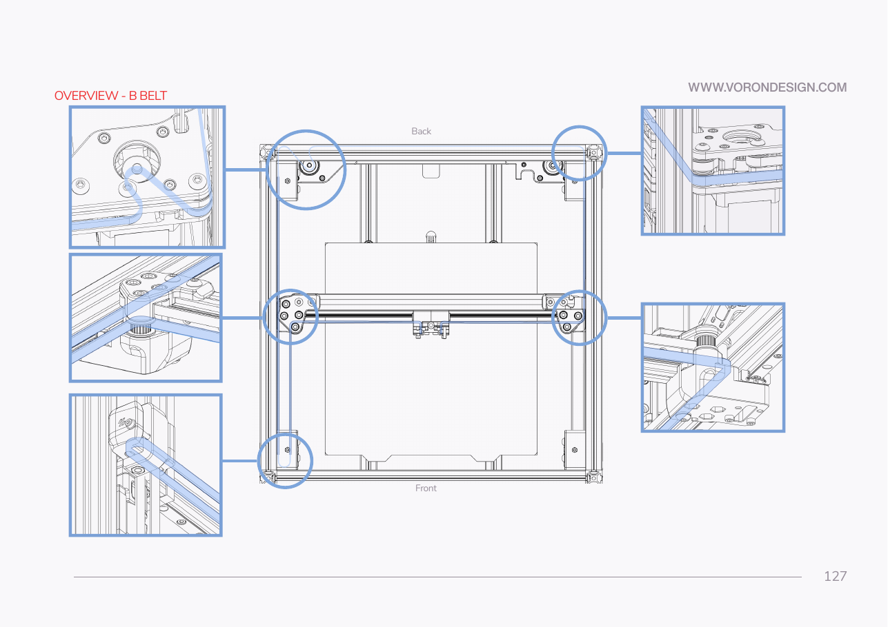 Step 07.4Trace the B belt path
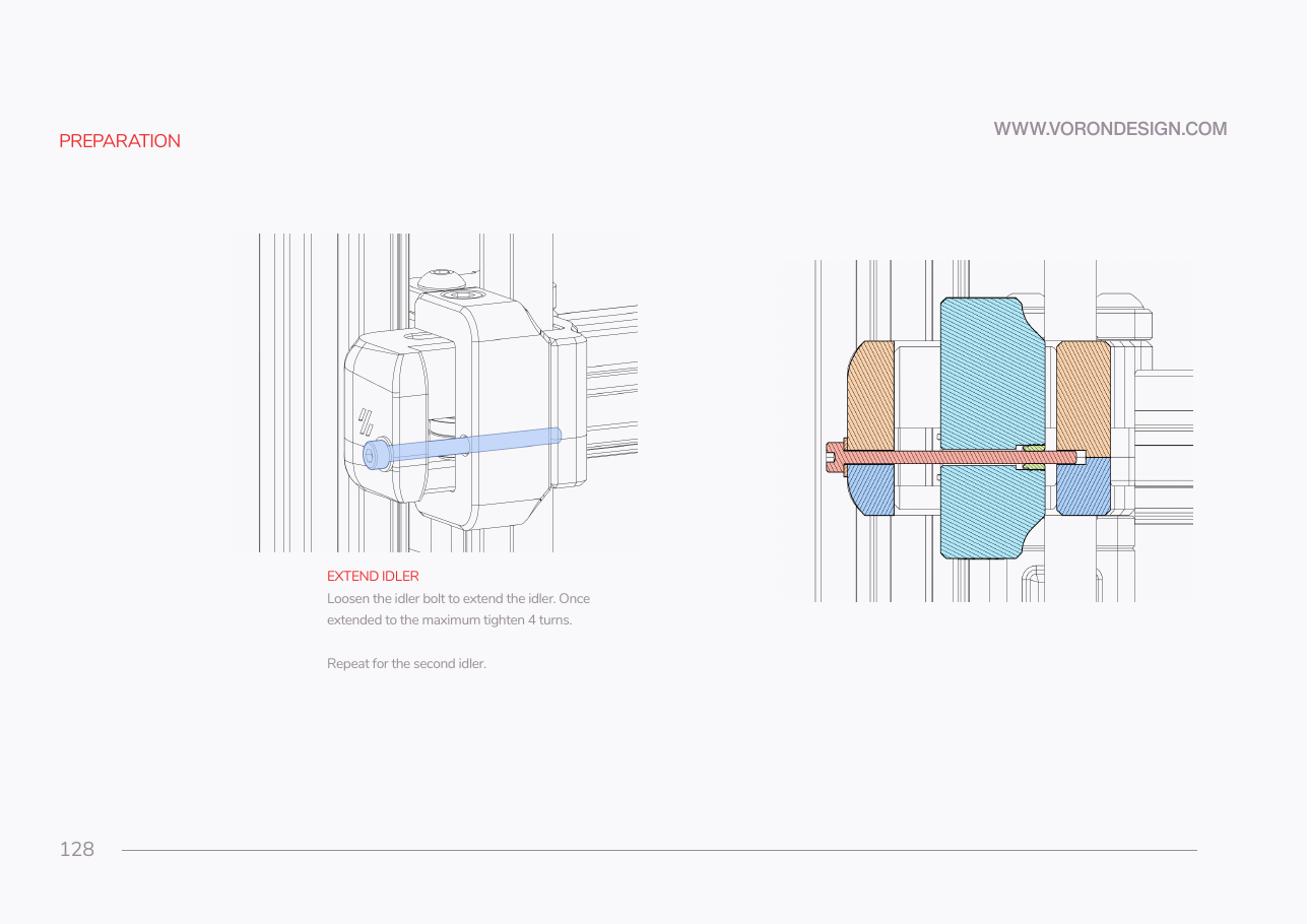 Step 07.5Set both front-idler tensionerswith a helper
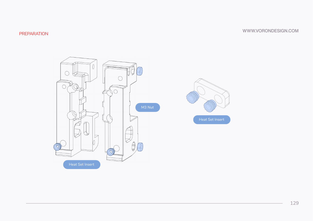 Step 07.6Fit the heat-set inserts and M3 nuts
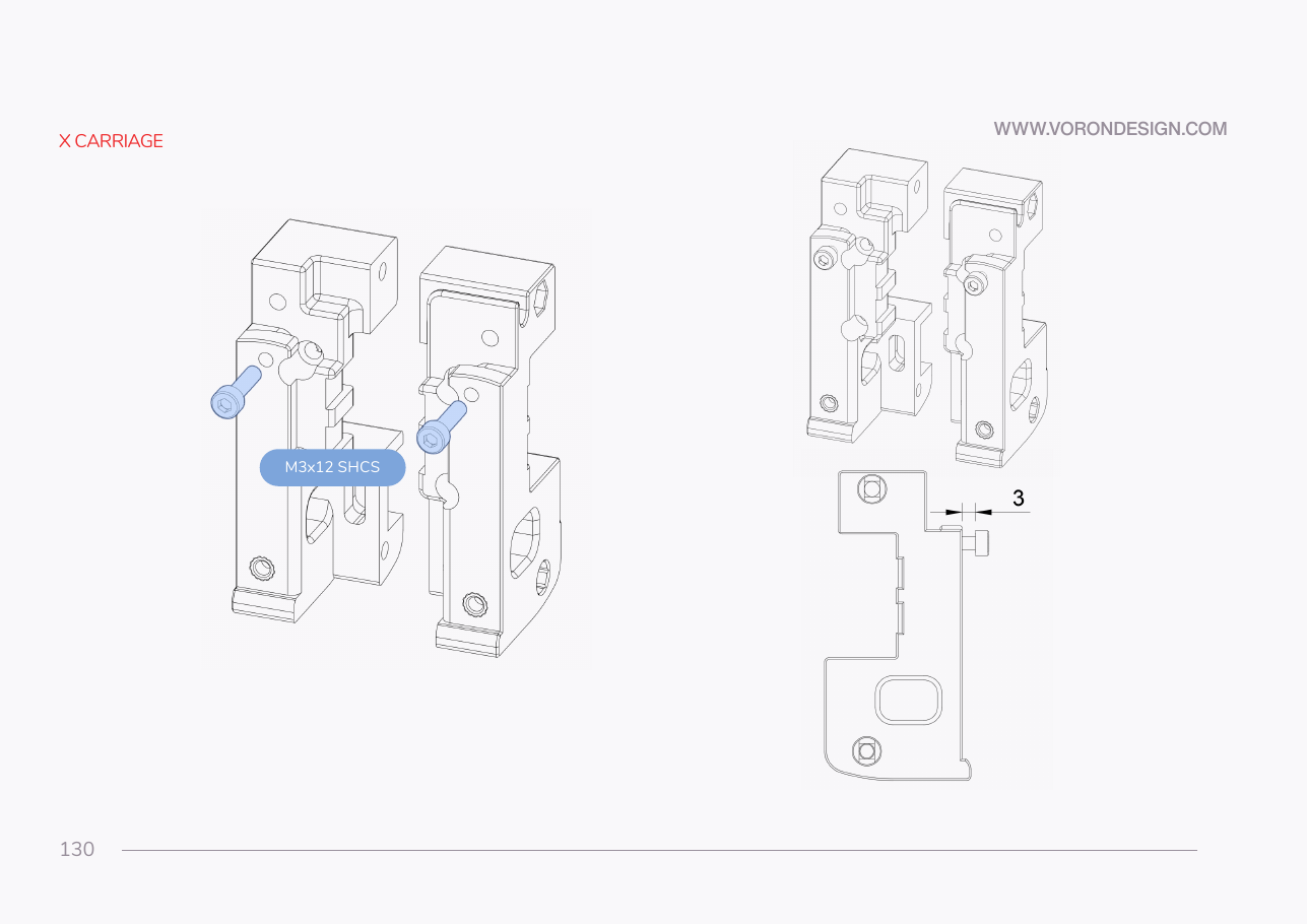 Step 07.7Set the two carriage stop screws to 3 mm
Step 07.8Cut both belts to the same length
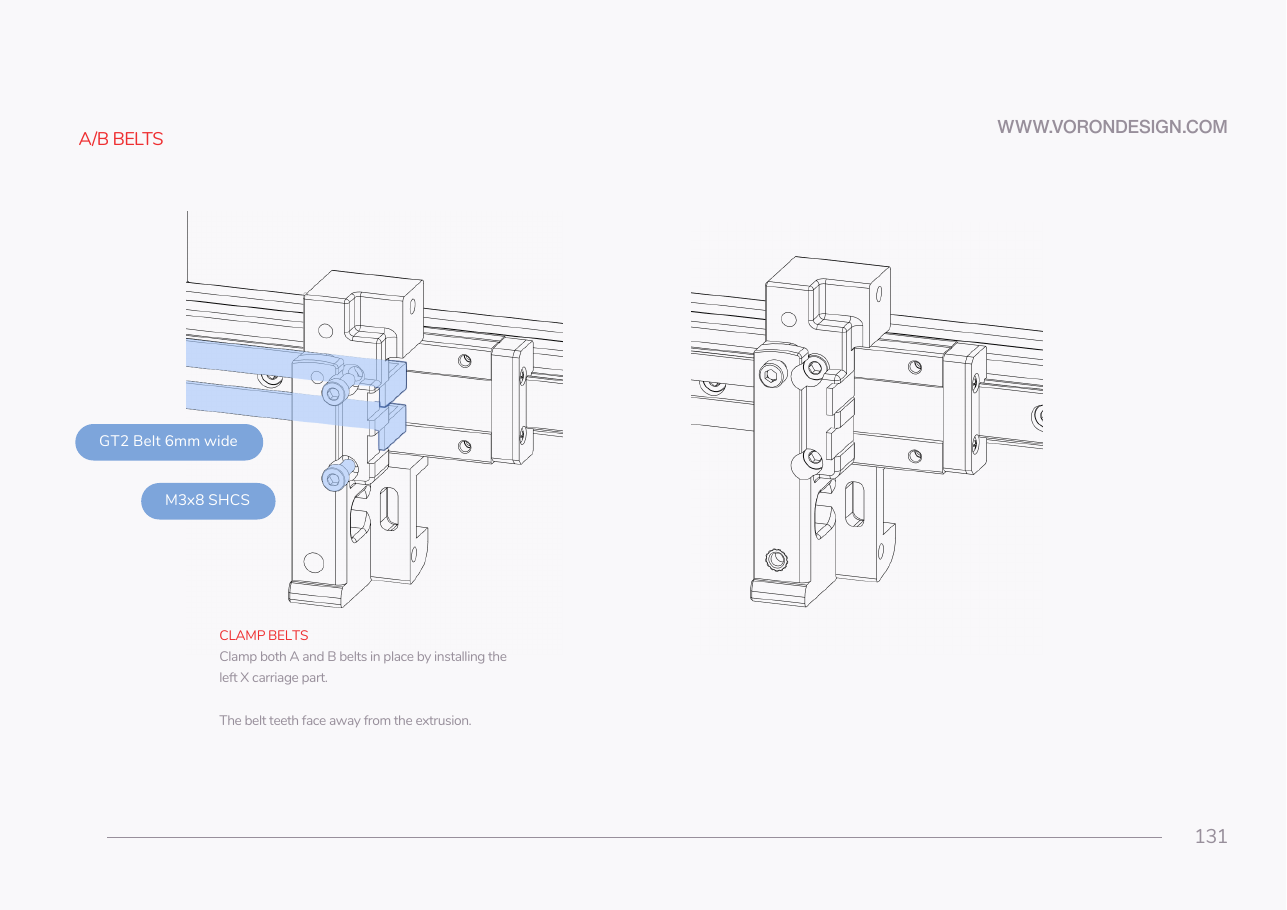 Step 07.9Clamp the first end of both belts in the left carriage half
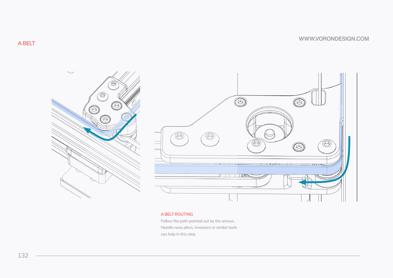 Step 07.10A belt: leave the carriage and turn at the left XY joint
Step 07.11A belt: run rearward up the left Y extrusion
Step 07.12A belt: turn 90° at the rear-left idler stack
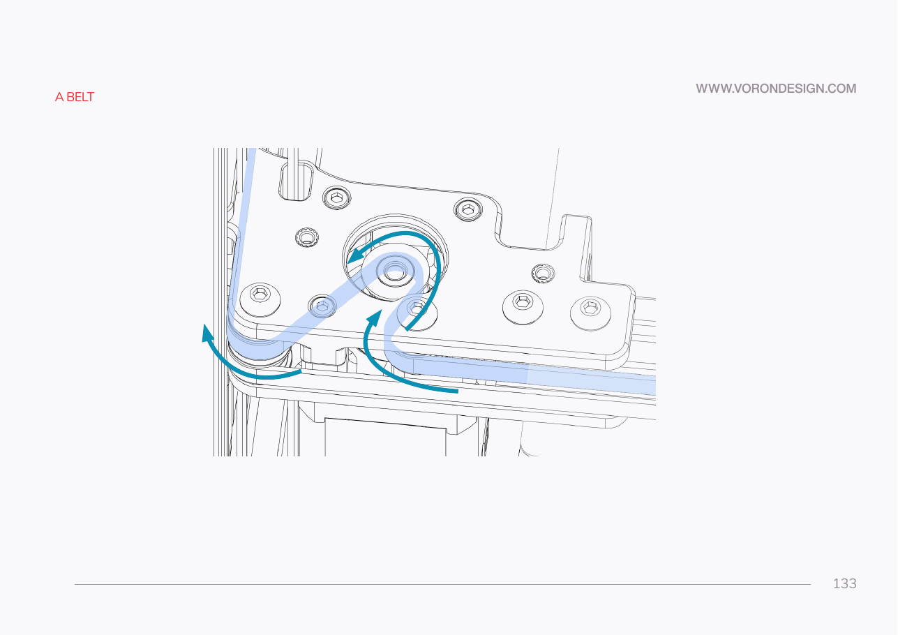 Step 07.13A belt: S-wrap the A drive motor pulley
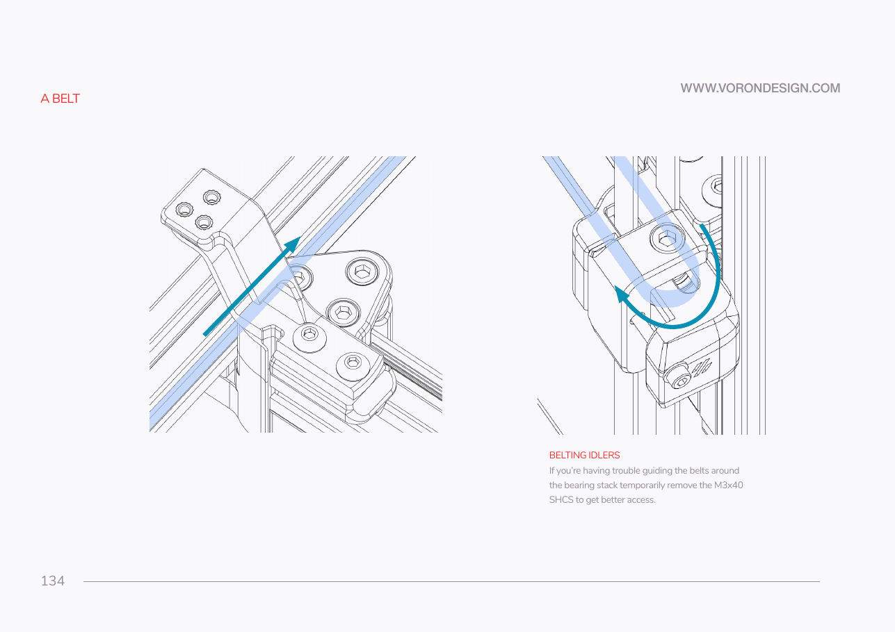 Step 07.14A belt: run forward down the right Y extrusion
Step 07.15A belt: U-turn at the front-right idler
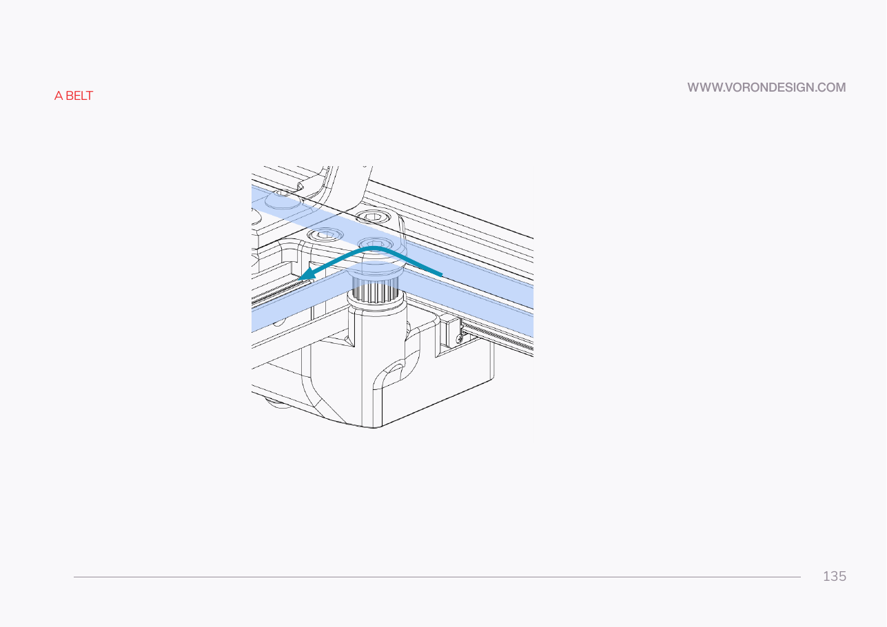 Step 07.16A belt: turn at the right XY joint and return to the carriage
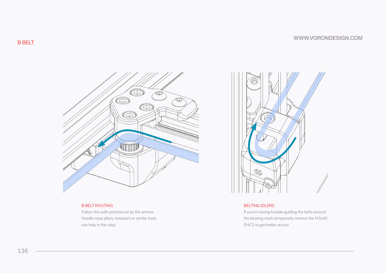 Step 07.17B belt: leave the carriage and turn teeth-on at the left XY joint
Step 07.18B belt: run forward and U-turn at the front-left idler
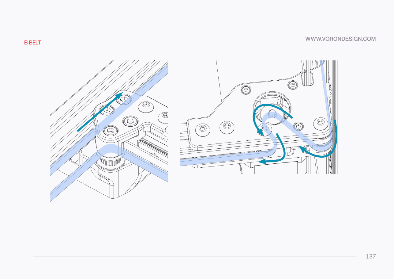 Step 07.19B belt: run rearward up the left outer run, past the left XY joint
Step 07.20B belt: S-wrap the B drive motor pulley
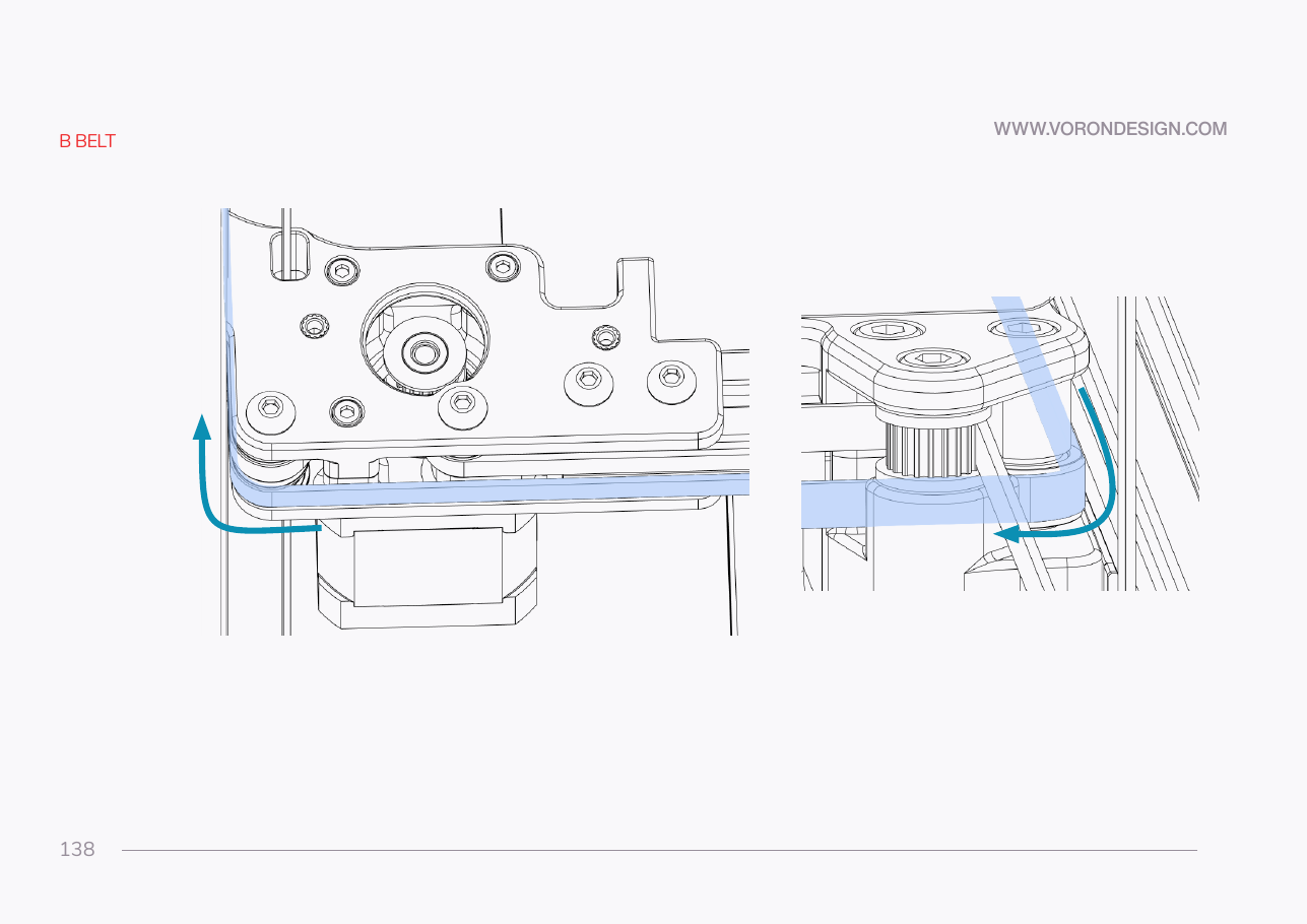 Step 07.21B belt: run right along the rear and turn 90° at the rear-right idler stack
Step 07.22B belt: run forward, turn smooth at the right XY joint and return to the carriage
Step 07.23Check both belts against the overviews before closing the carriagewith a helper
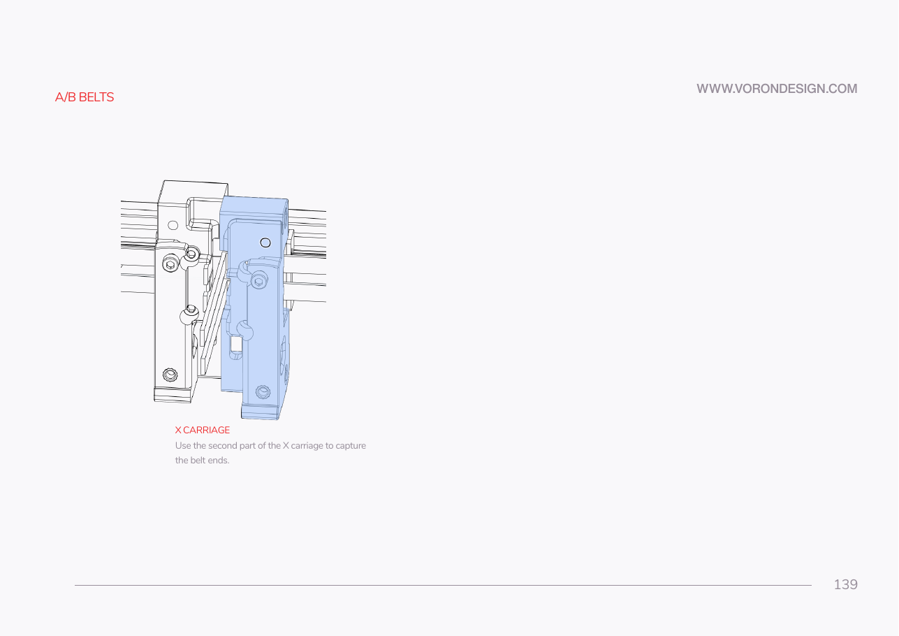 Step 07.24Fit the right X carriage half to capture the belt ends
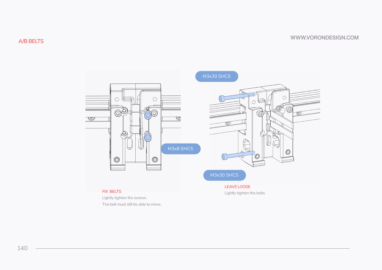 Step 07.25Fix the belts, lightly
Step 07.26Fit the carriage bolts and leave them loose
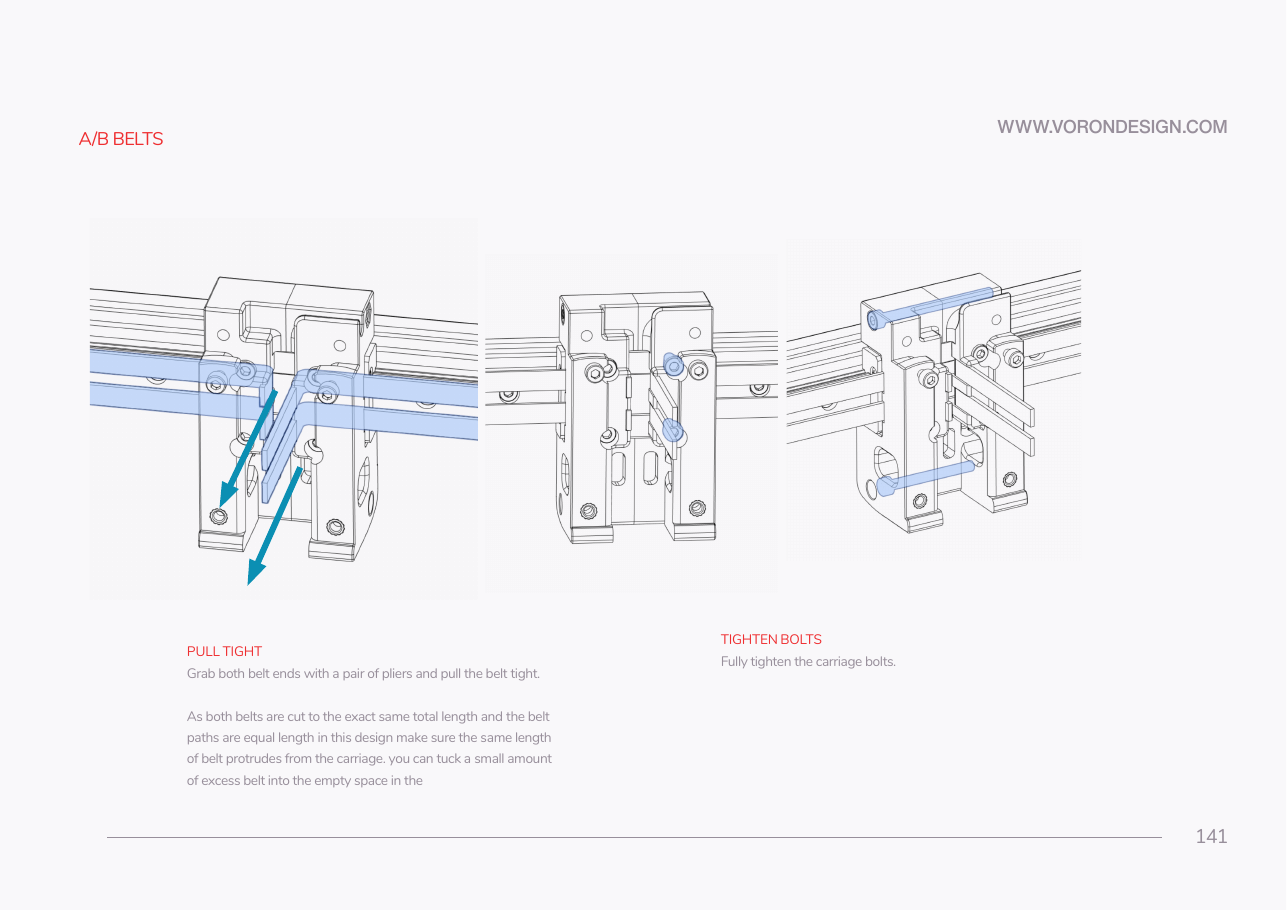 Step 07.27Pull both belts tight and equalise the tailswith a helper
Step 07.28Tighten the carriage bolts
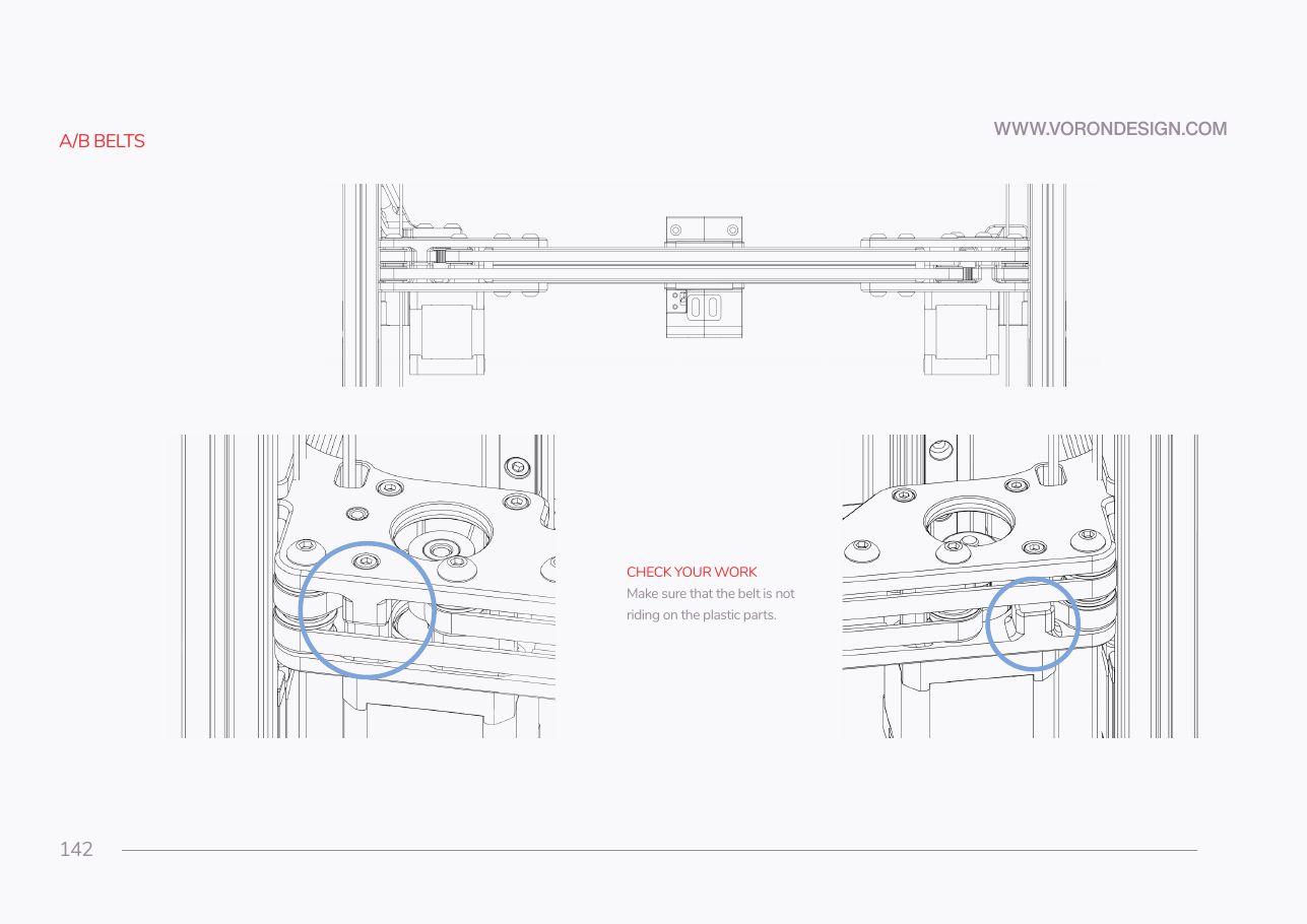 Step 07.29Belt-rub inspection at every idler stackwith a helper
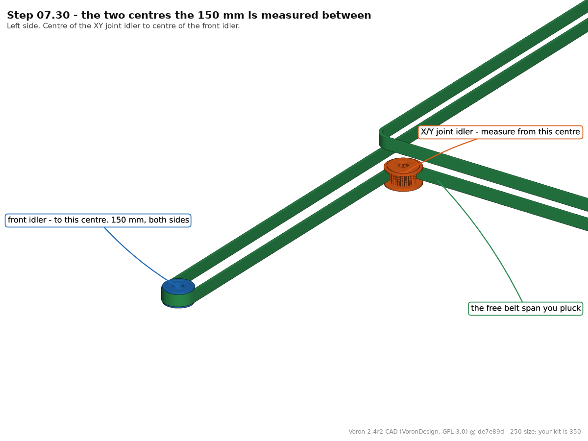 Step 07.30Set the 150 mm measuring spanwith a helper
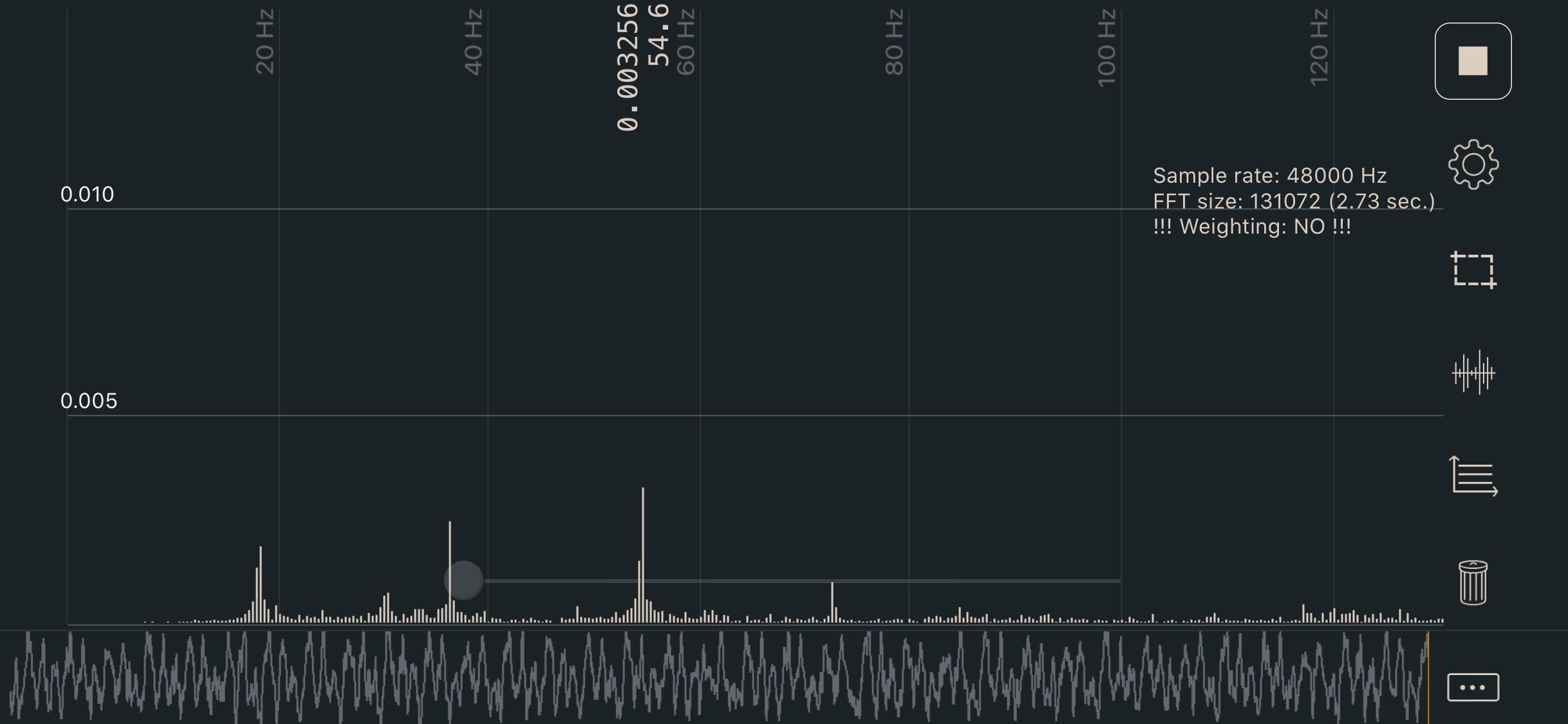 Step 07.31Read both belts with the phonewith a helper
Step 07.32Bring both belts to ~110 Hzwith a helper
Step 07.33Move the gantry, return, and re-check
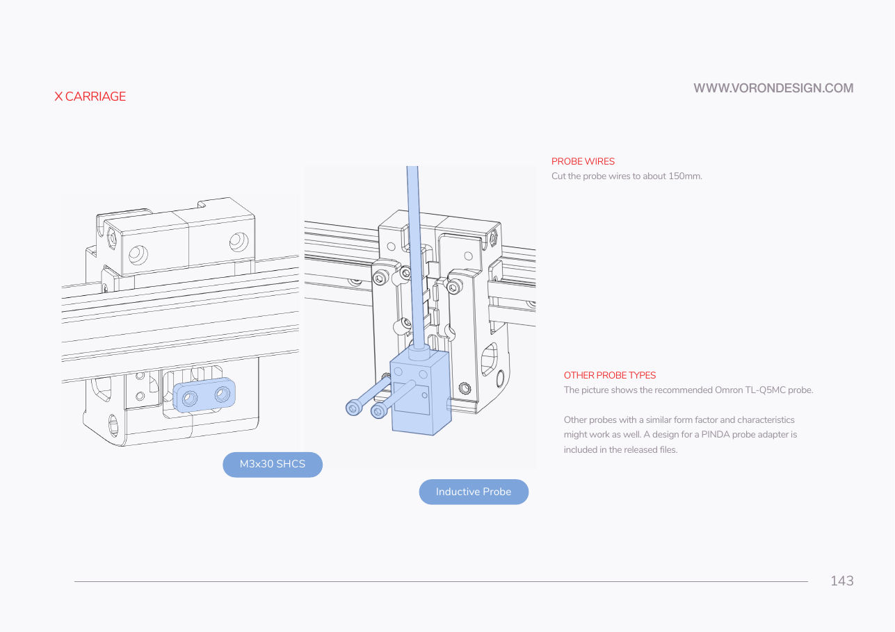 Step 07.34Insulate the probe and keep its lead whole
Step 07.35Fit the probe and its retainer bracket
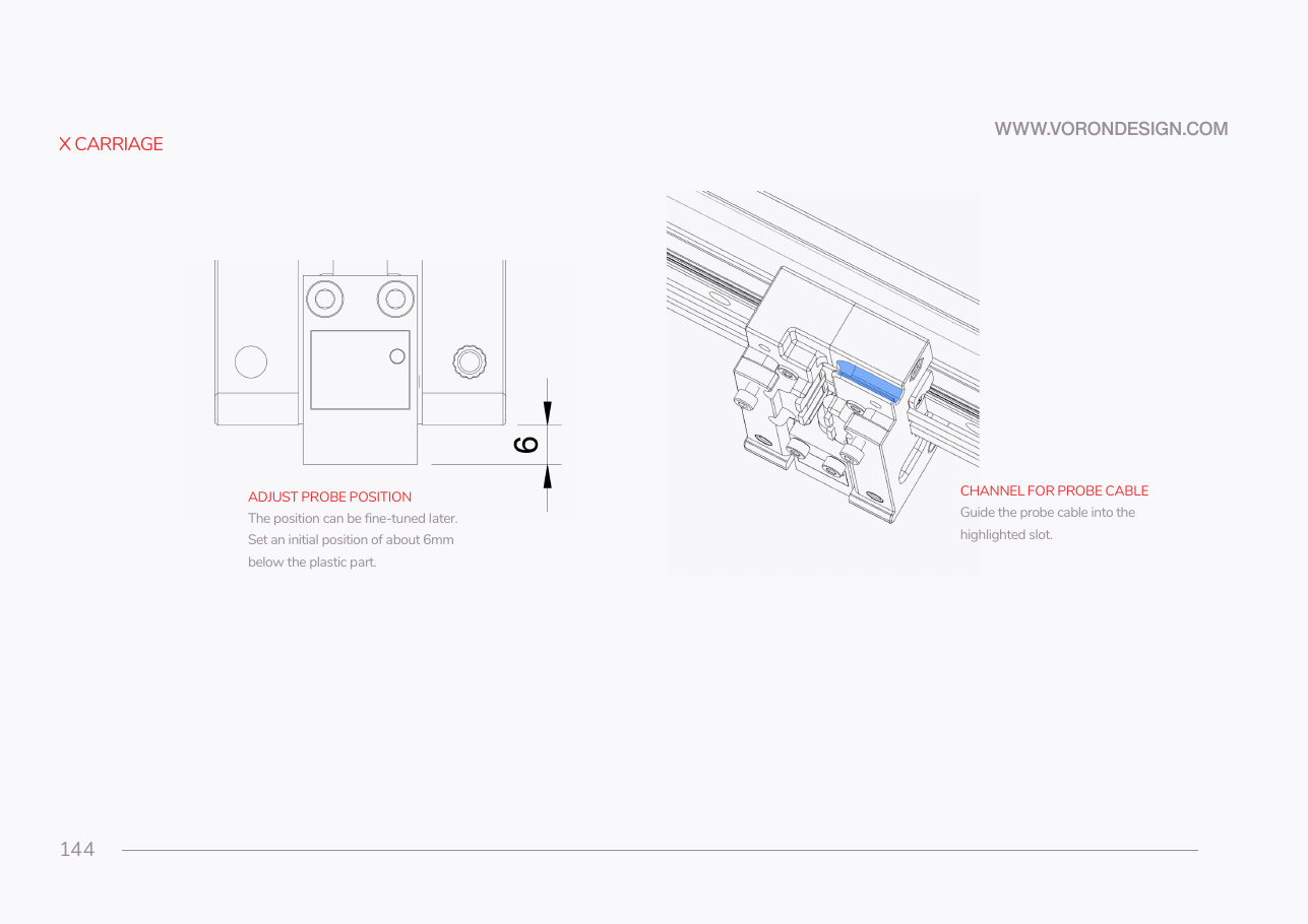 Step 07.36Set the probe heightwith a helper
Step 07.37Route the probe cablewith a helper
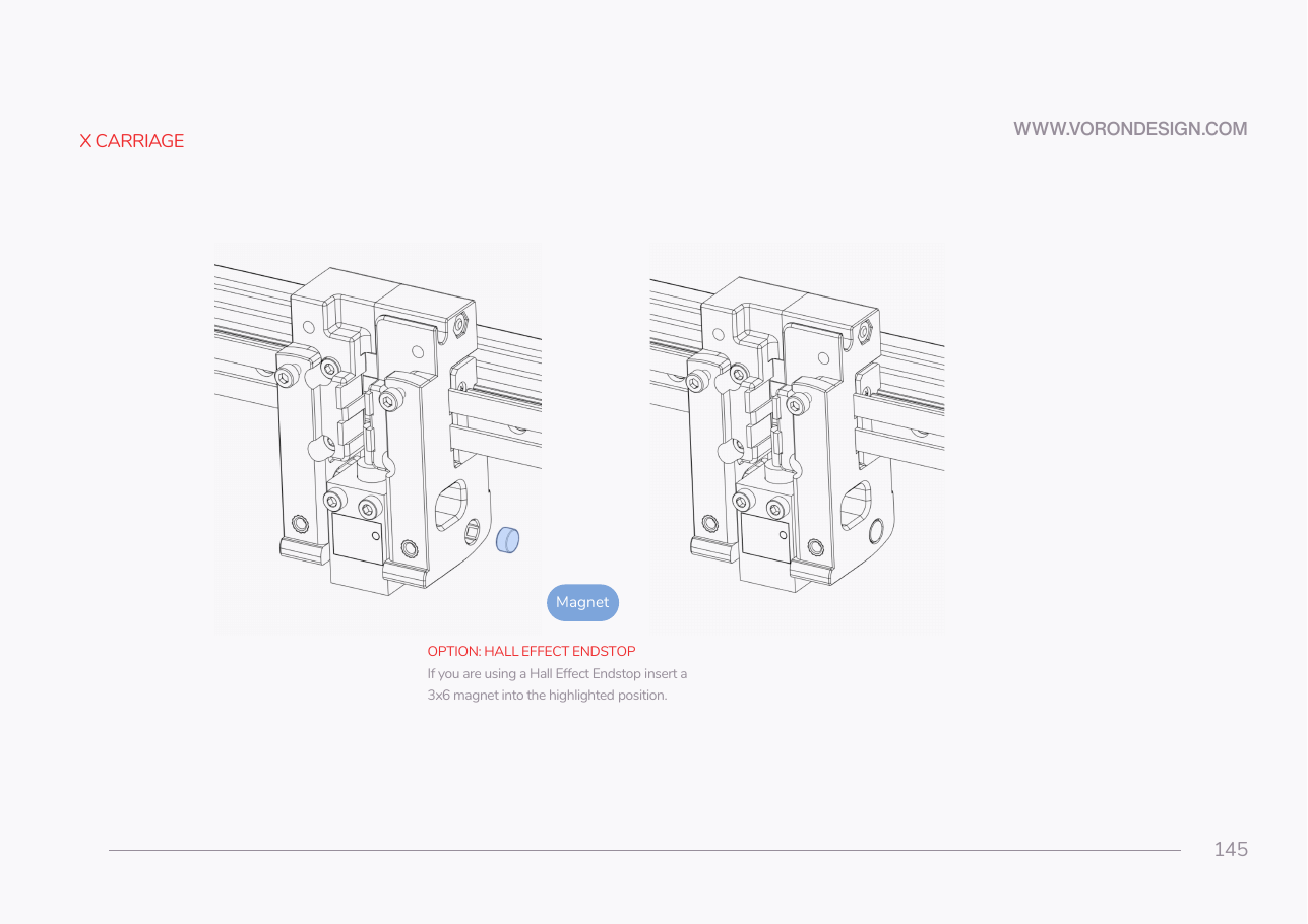 Step 07.38Hall-effect endstop magnet: skip
Gather per session — what to lay out before each bench segment.
- Steps 07.1–07.5 · ~25 min — Already on the bench: the two front-idler M3×40 SHCS; the two front-idler M3 washers
- Steps 07.6–07.8 · ~30 min — Fasteners, Tools & Misc box: M3 heat-set insert ×4; M3 nut ×2; M3×12 SHCS ×2 · Printed parts:
x_frame_V2TR_MGN12_left×1 (bin 07-X);x_frame_V2TR_MGN12_right×1 (bin 07-X);probe_retainer_bracket×1 (bin 07-X) · Tools and consumables: Gates 2GT open belt, 6 mm wide, two equal lengths - Steps 07.9–07.28 · ~80 min — Fasteners, Tools & Misc box: M3×8 SHCS ×4; M3×30 SHCS ×2 · Already on the bench: the left X carriage half; both cut belts, marked A and B; the A belt; the B belt; the right X carriage half; both belts, tails loose
- Steps 07.29–07.33 · ~30 min — nothing to lay out
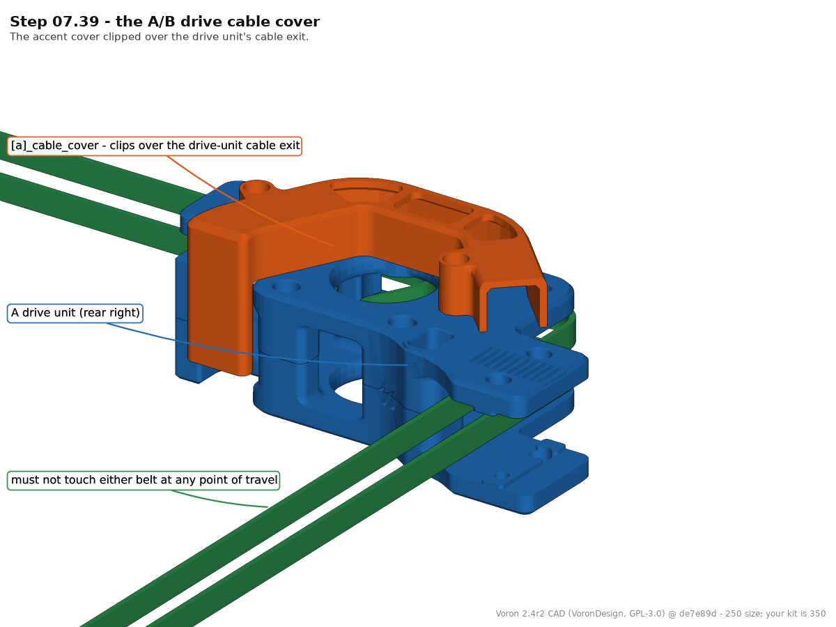
- Steps 07.34–07.39 — Cable Kit 2.4-350 box: Omron TL-Q5MC inductive probe ×1 · Fasteners, Tools & Misc box: M3×30 SHCS ×2 · Printed parts:
[a]_cable_cover×1 (bin 07-X) · Tools and consumables: fibreglass tape 2×12 cm · Already on the bench: the probe retainer bracket