Chapter 10 — Wiring and Checkpoint #1
Start the chapter · Resume · Read the whole chapter on one page
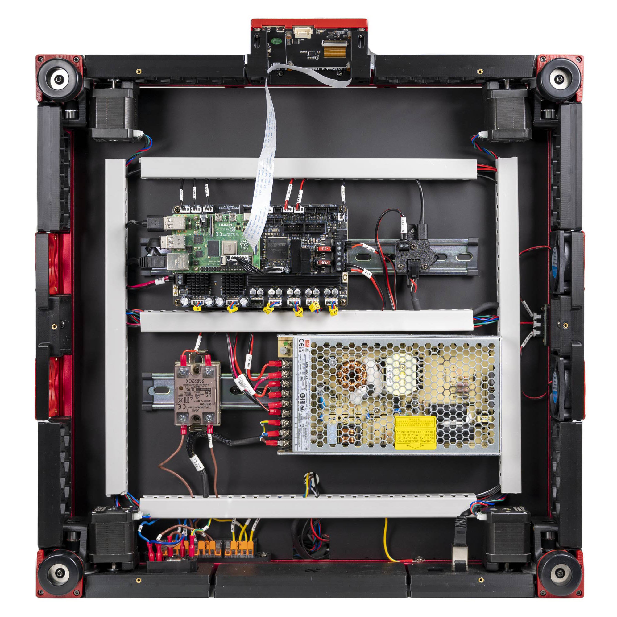 Step 10.1Empty the bay and set the end state
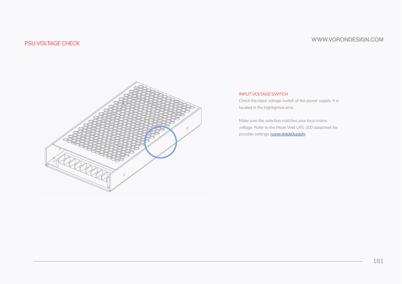 Step 10.2Set the PSU input-voltage selector
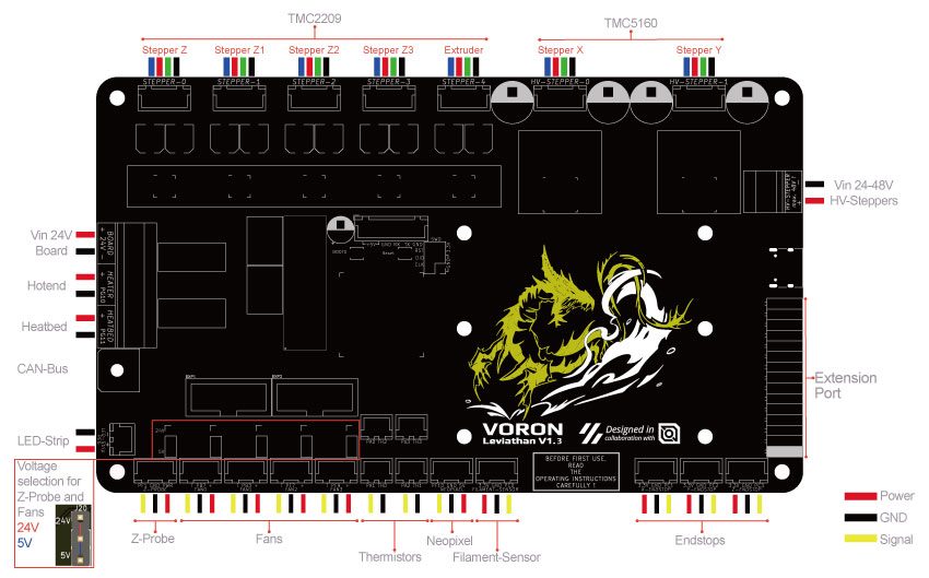 Step 10.3Confirm the Leviathan voltage-selection jumpers are off
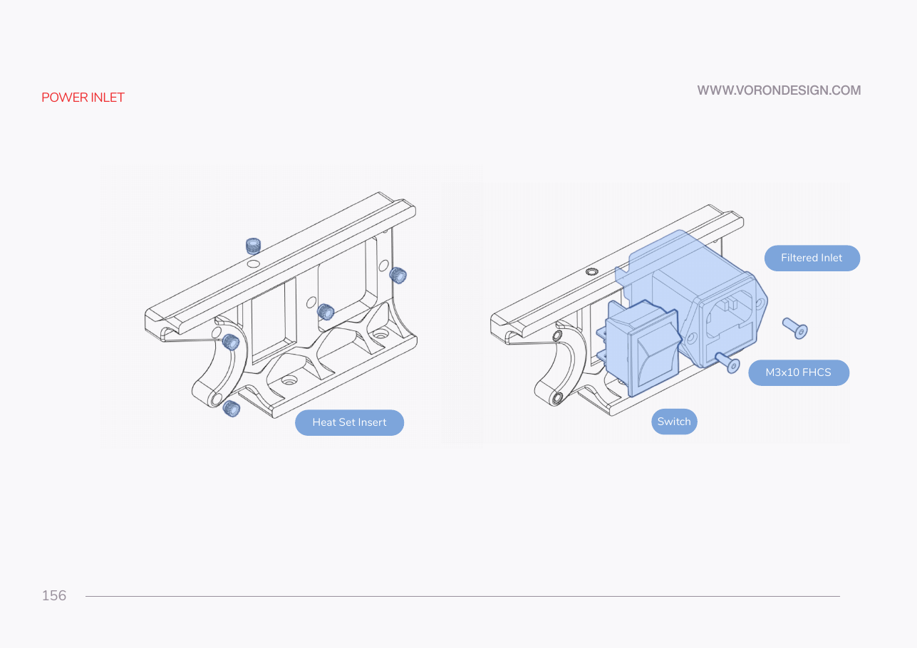 Step 10.4Fit the AC inlet into the printed plug panel
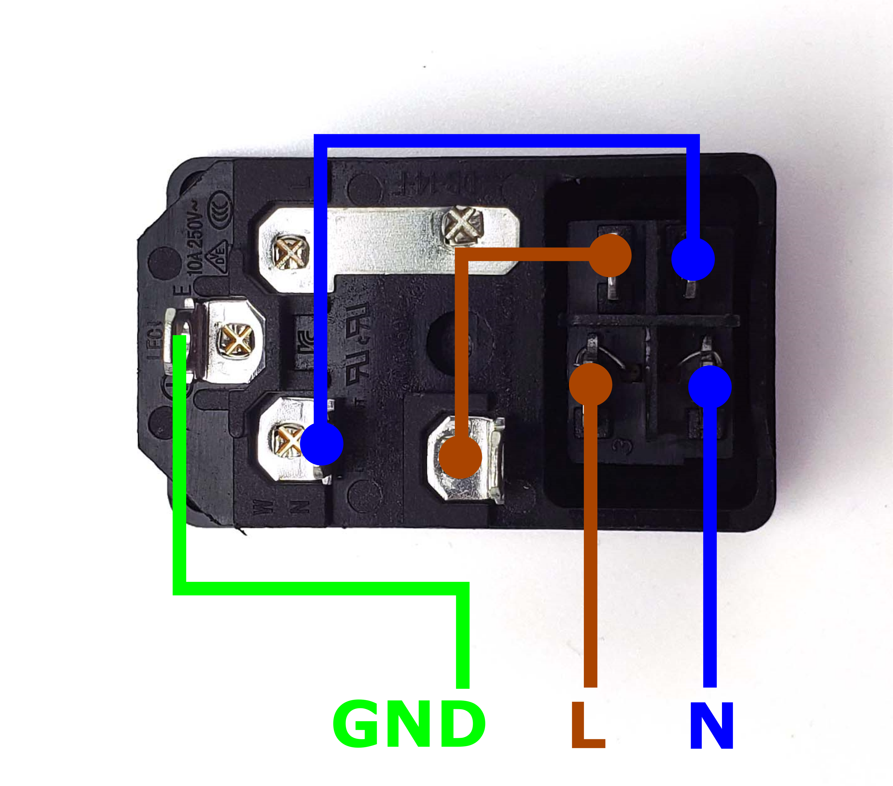 Step 10.5Verify the pre-wired inlet before you trust it
 Step 10.6Mount the plug panel to the rear frame
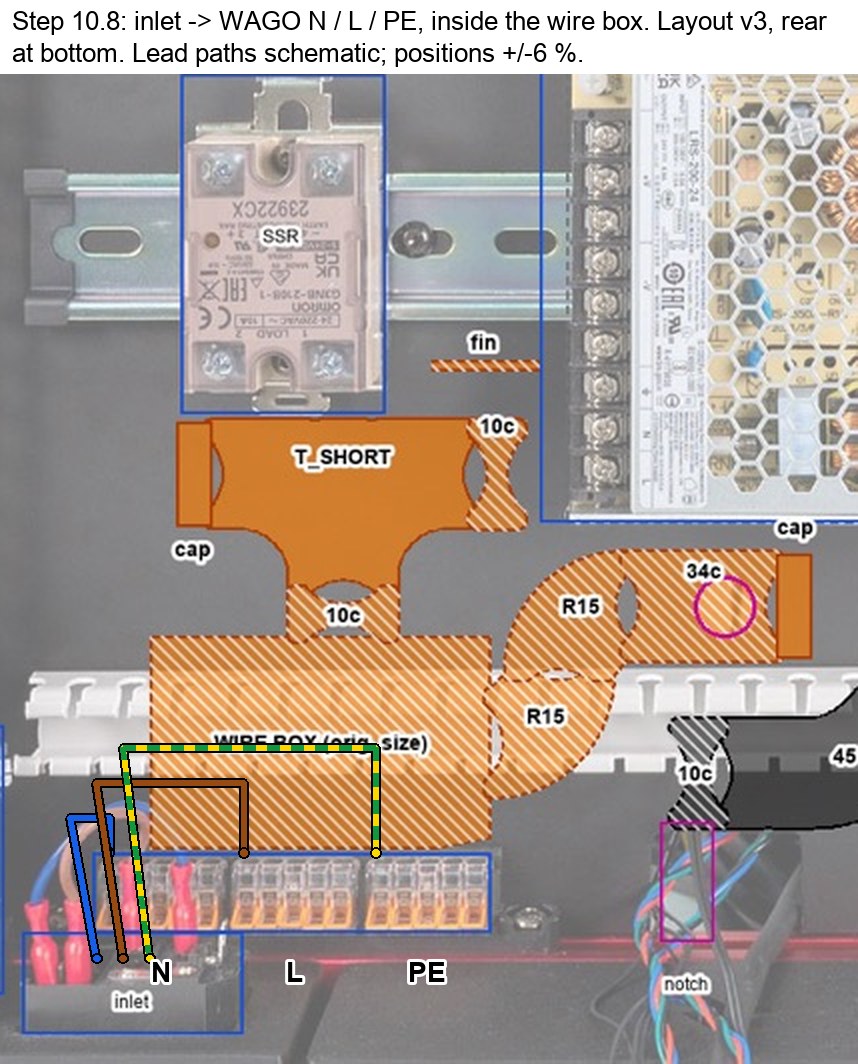
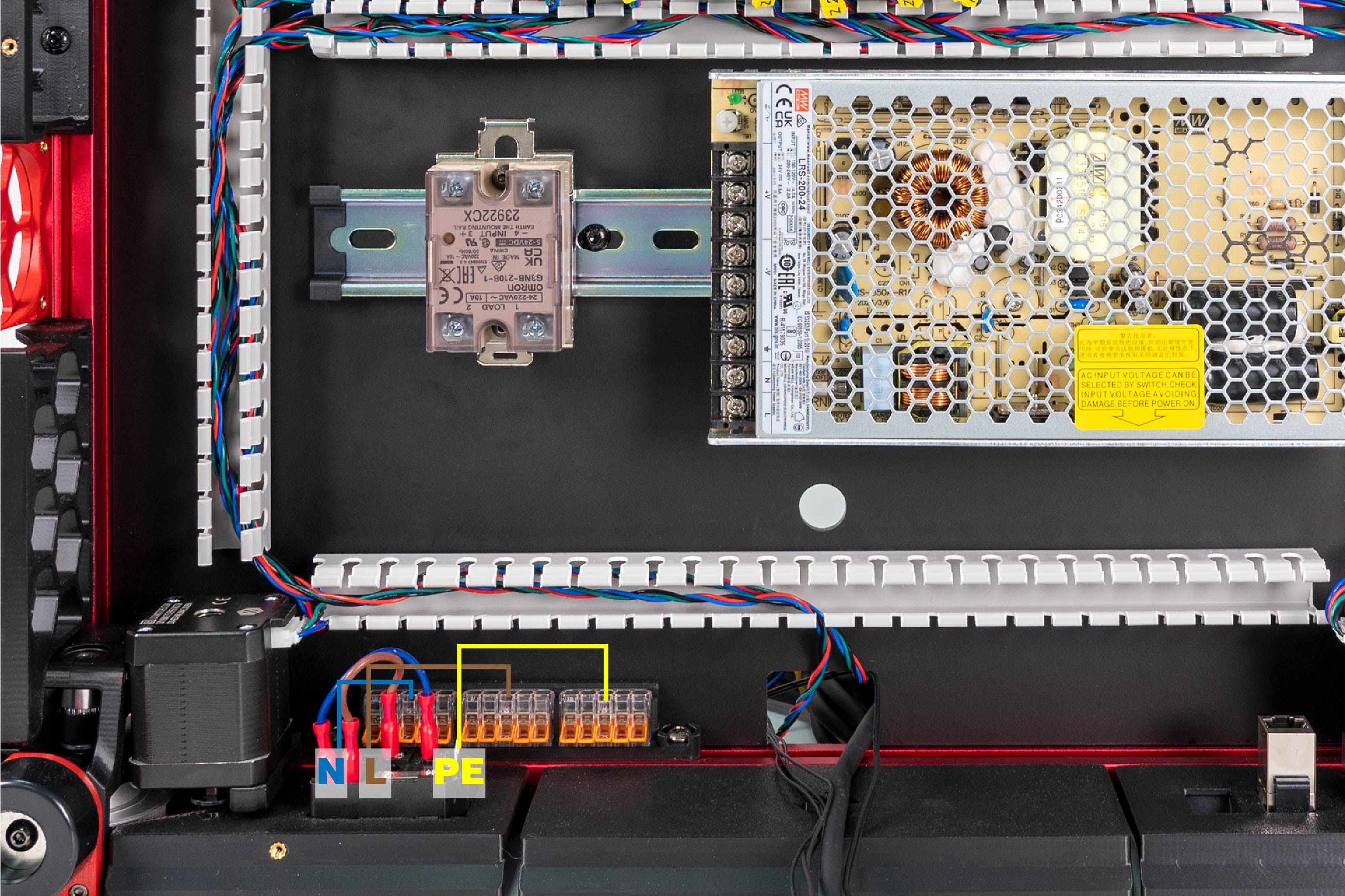 Step 10.7Populate and label the WAGO bus
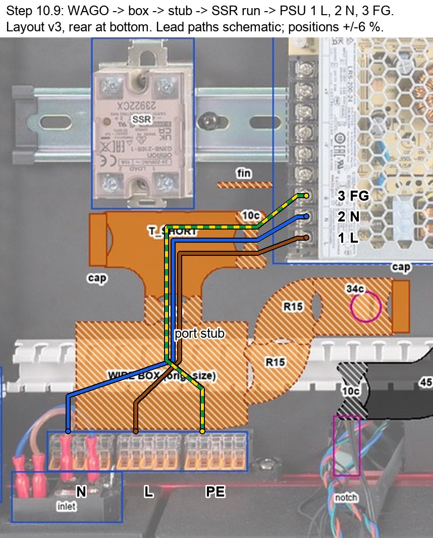
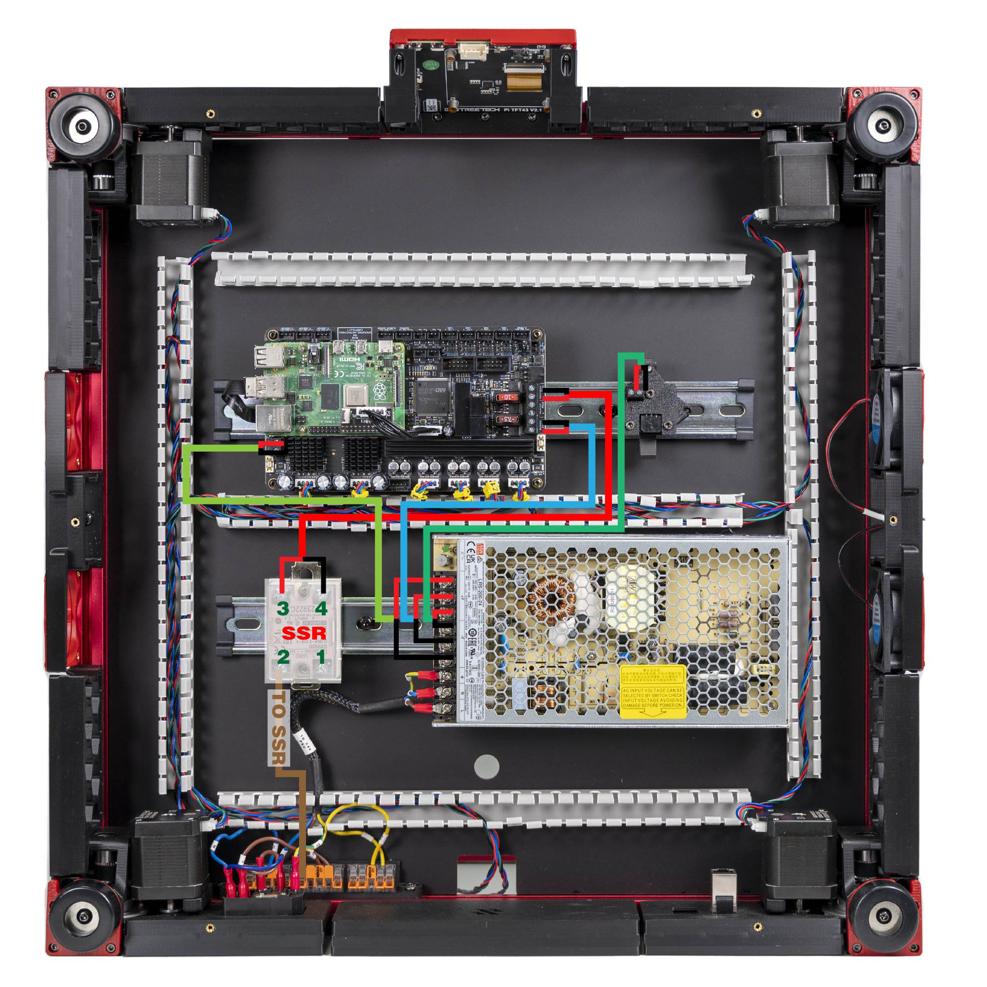 Step 10.10Read the SSR terminal numbers before you wire it
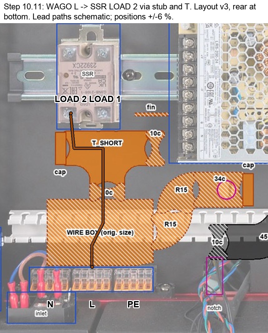 Step 10.11Live from the WAGO bus → SSR LOAD 2
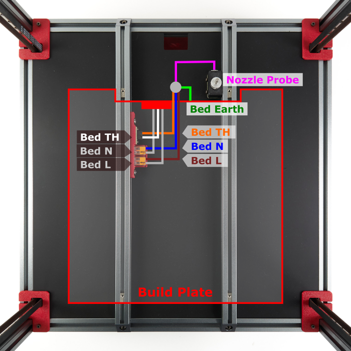 Step 10.12Bed harness into the bed WAGO breakout
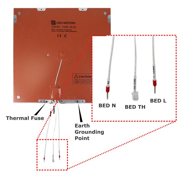 Step 10.13Measure the bed heater before you connect it
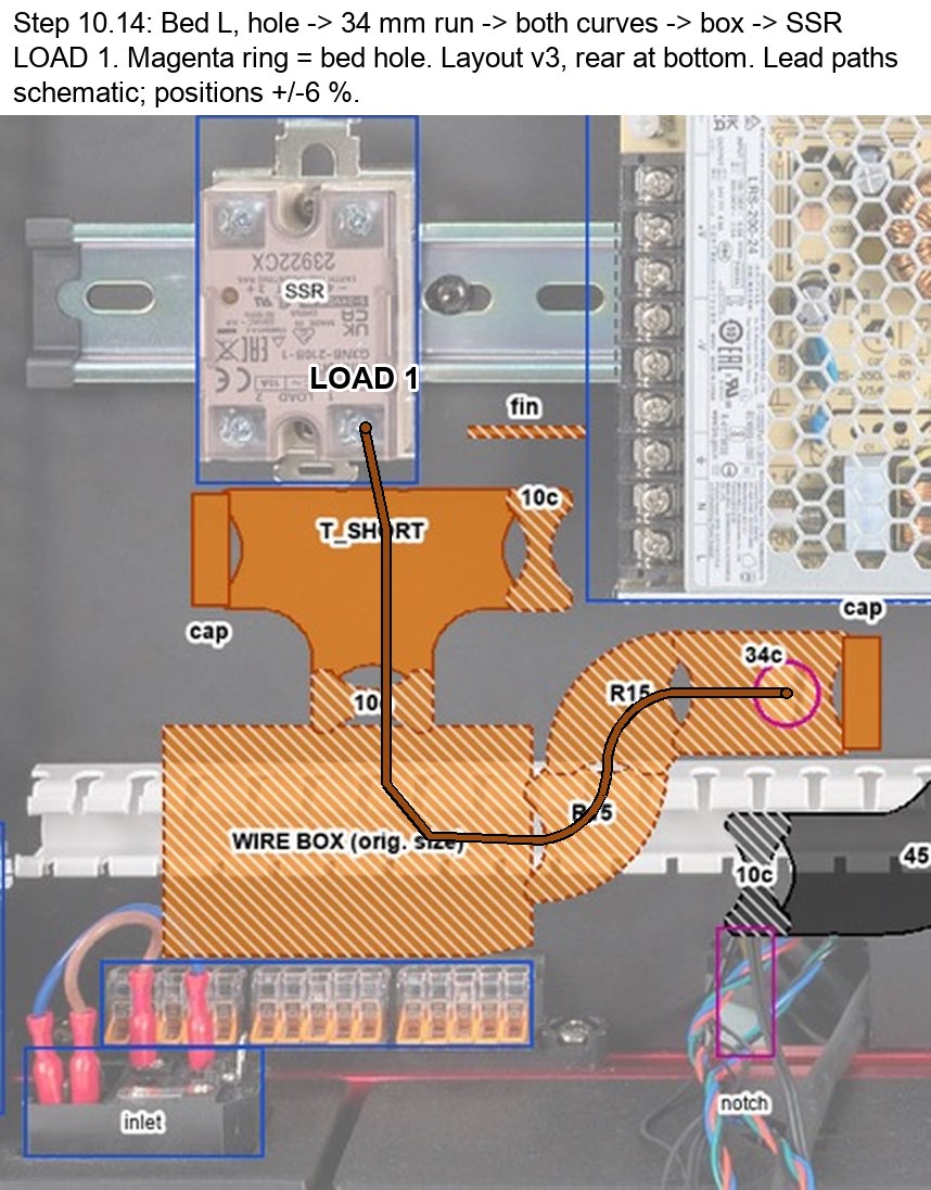 Step 10.14Bed Live → SSR LOAD 1
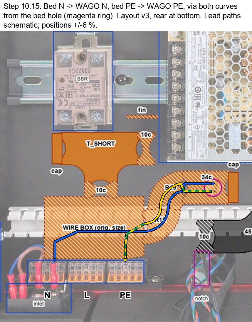 Step 10.15Bed Neutral and bed PE → the WAGO bus
Step 10.17De-energise and set up
Step 10.18Colour groups are shorted
Step 10.19L, N and PE are isolated from each other
Step 10.20The switch actually switches
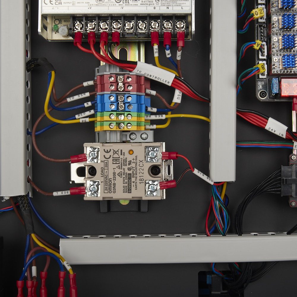 Step 10.21The SSR is open when unpowered
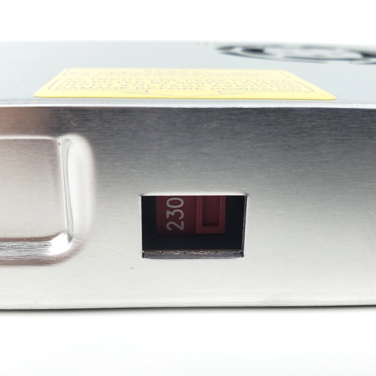 Step 10.22Re-check the voltage selector
Step 10.23First power-on, then off again
Step 10.24PSU → Leviathan board supply
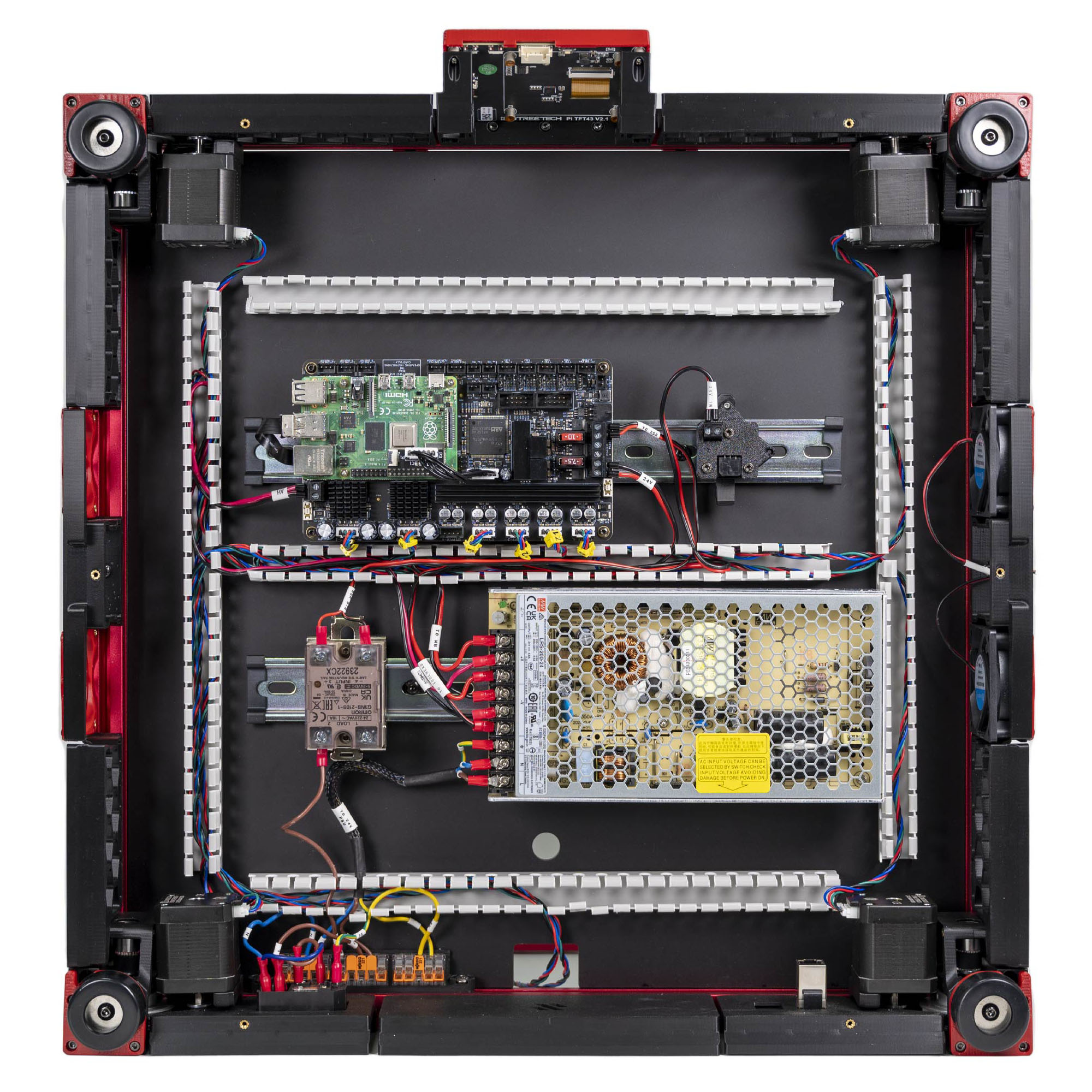 Step 10.25PSU → Leviathan HV stepper supply
 Step 10.26PSU → USB adapter PCB (toolhead 24 V)
Step 10.27Leviathan HEATBED → SSR INPUT
Step 10.28Set the FAN2 and FAN3 jumpers to 24 V
Step 10.29Meter the 24 V rail for shorts
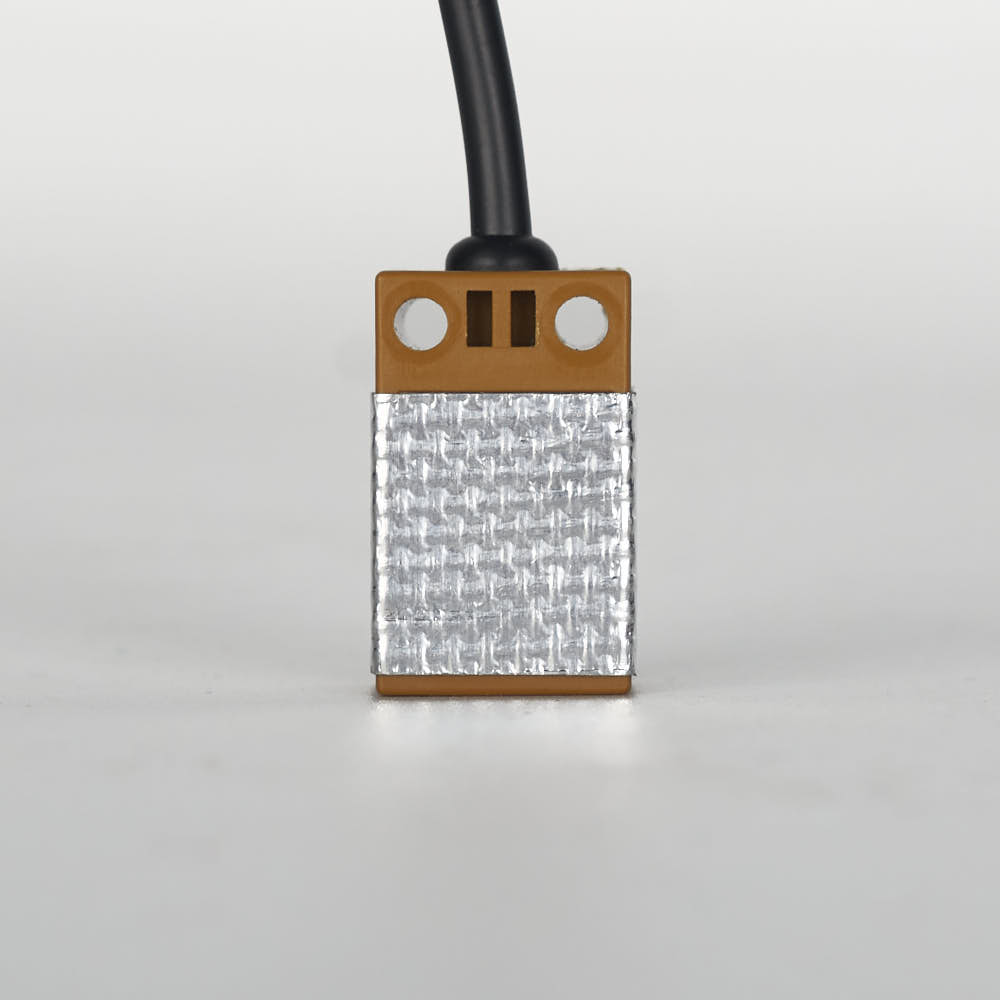 Step 10.30Confirm the inductive probe's tape
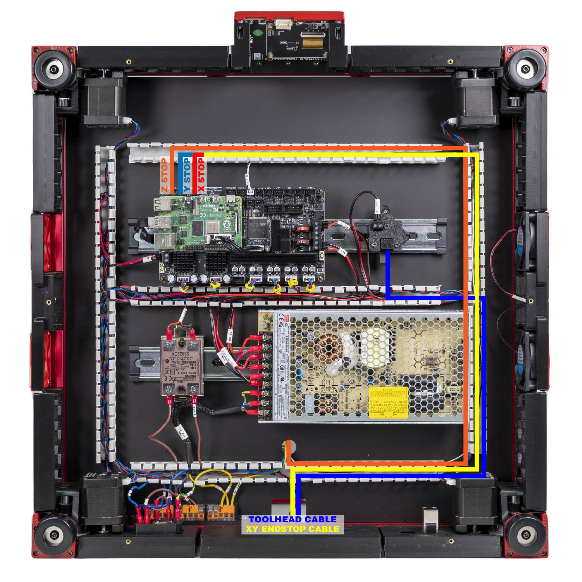
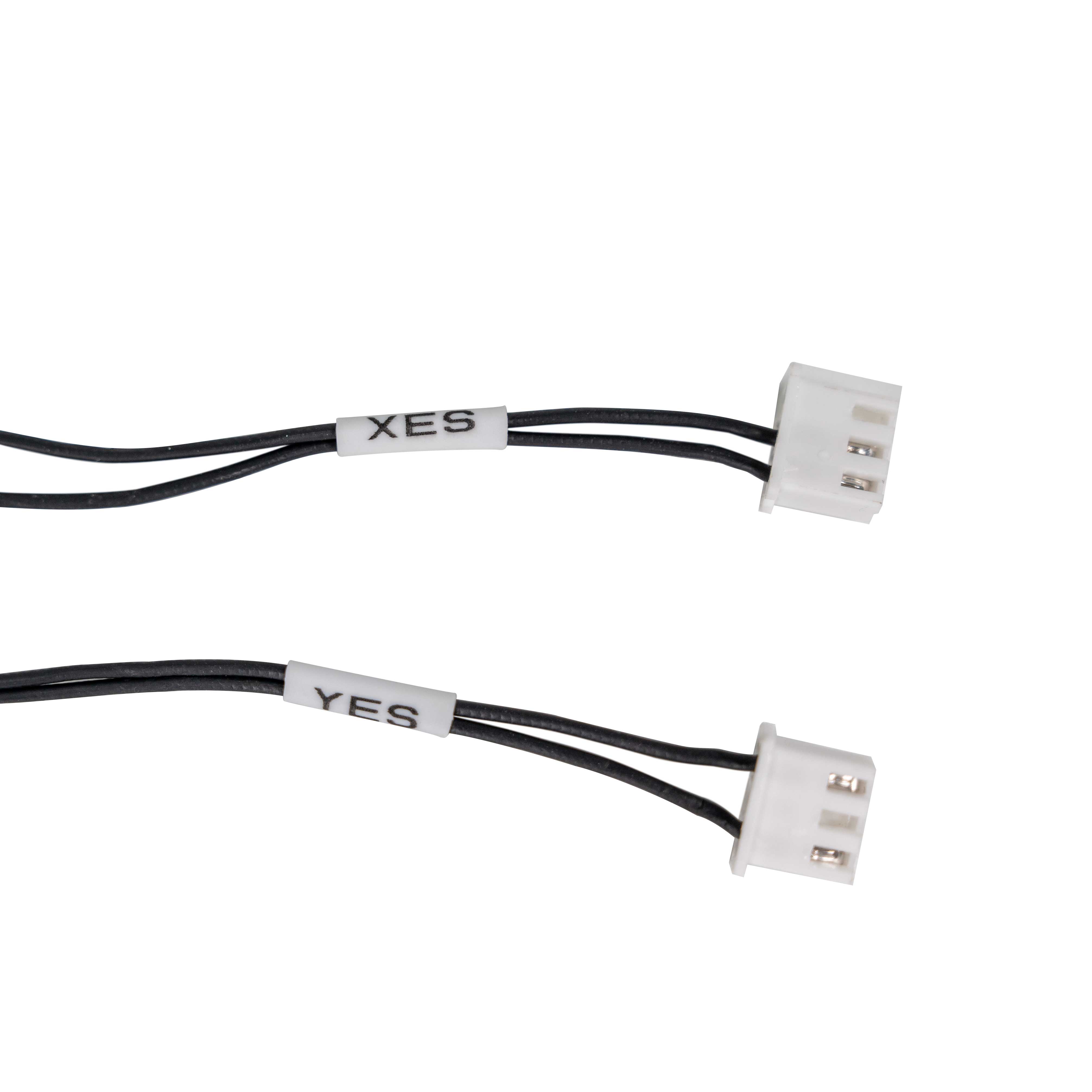 Step 10.31Read the XY endstop cable labelswith a helper
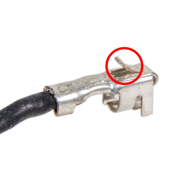 Step 10.32Repin the XY endstop cable (only if labelled X Stop / Y Stop)
Step 10.33XY endstop cable → the gantry PCB
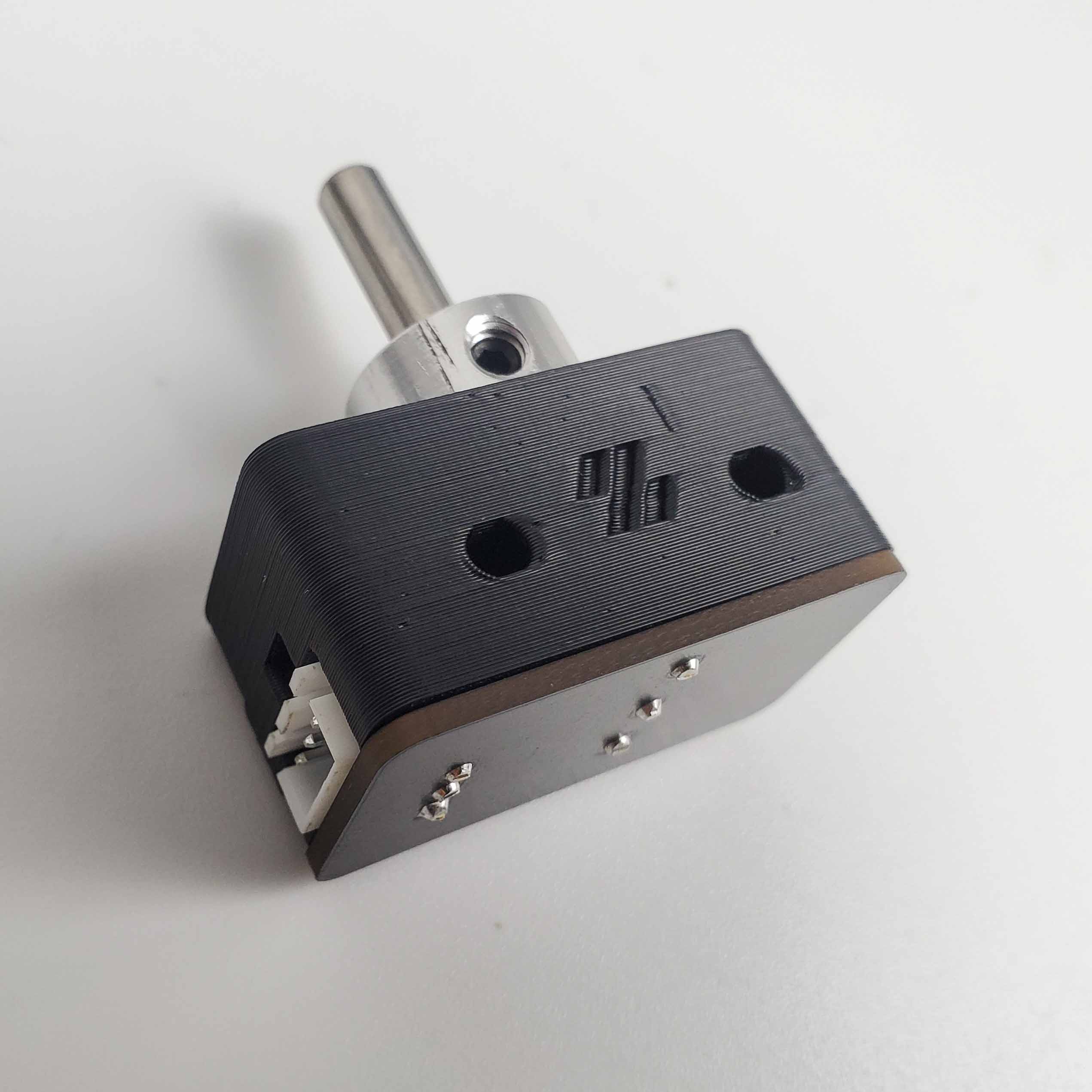 Step 10.34Nozzle-probe (Z endstop) cablewith a helper
Step 10.35Assemble the eight COB light-strip mounts
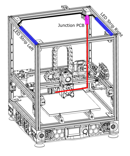 Step 10.36Mount the COB strips left and rightwith a helper
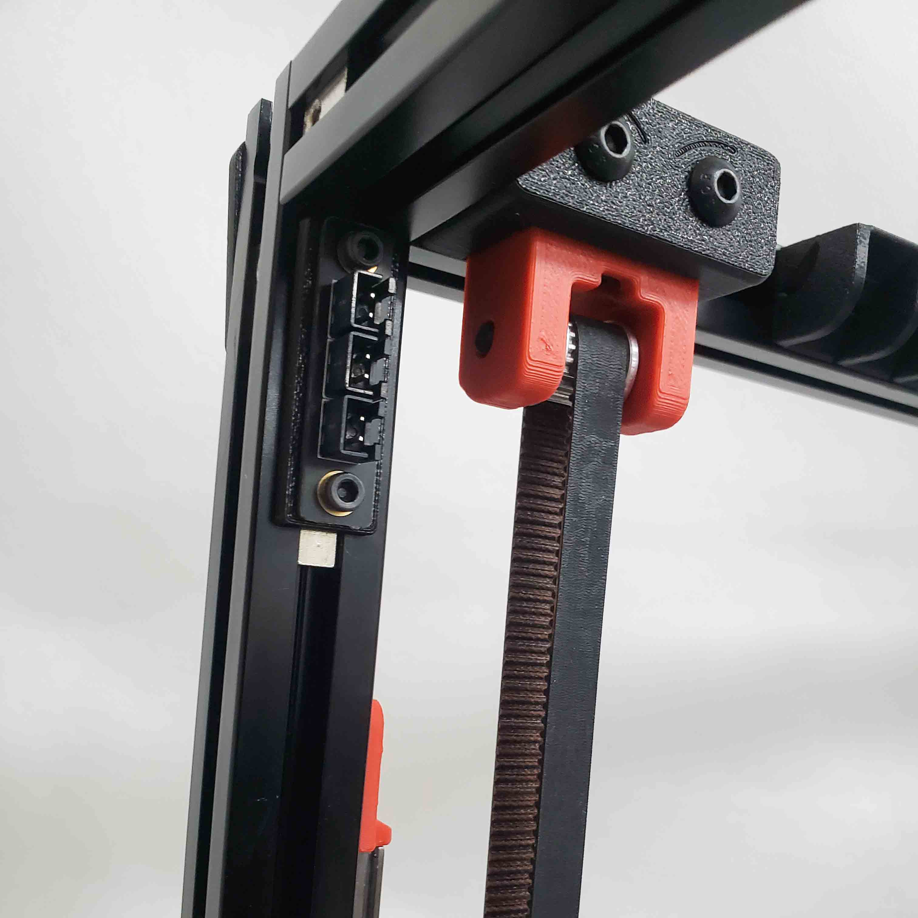 Step 10.37Mount the LED junction PCB on its spacer
Step 10.38Route the LED lead down to the deck and close the slots
Step 10.39Chamber thermistor, if your batch includes one
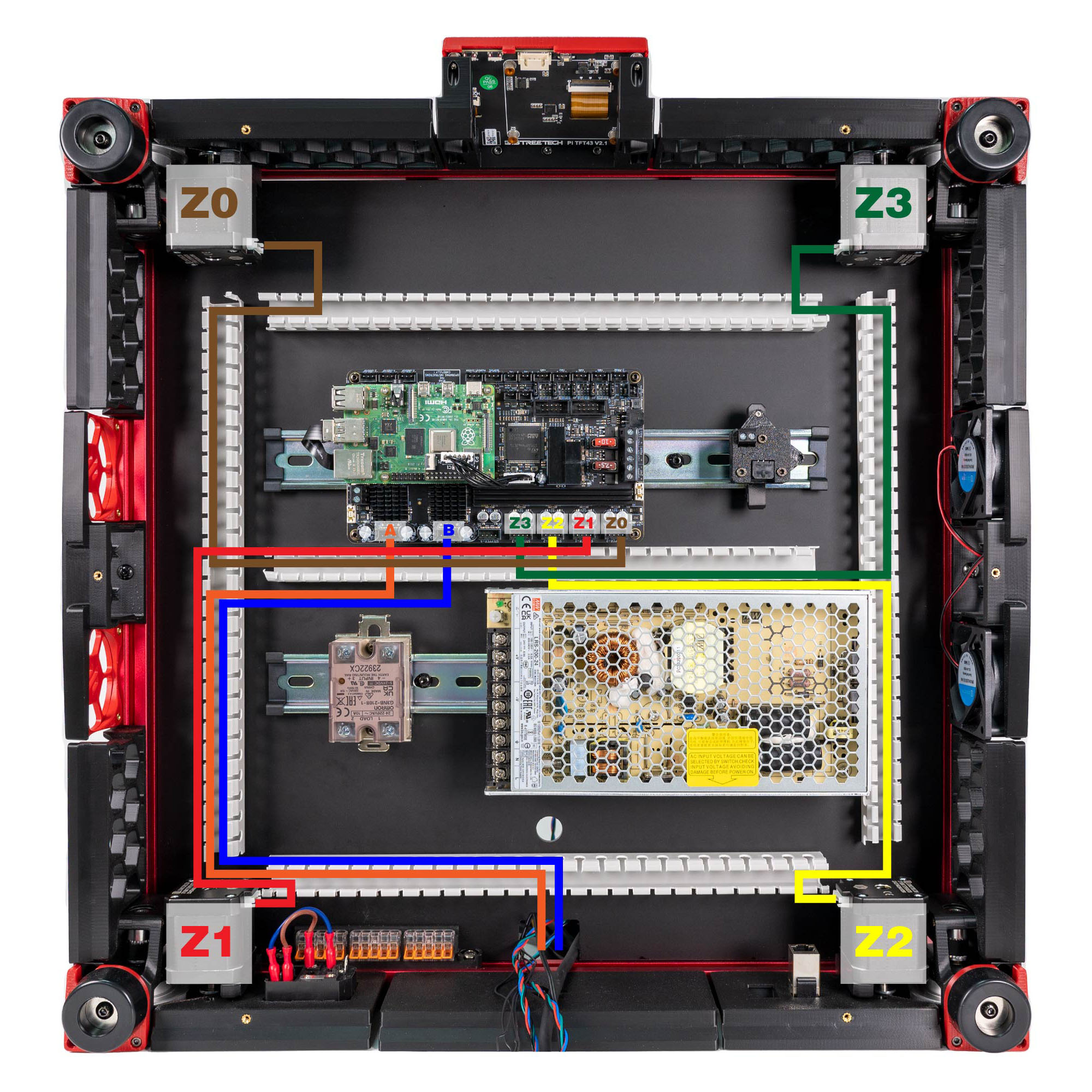 Step 10.40Tag every stepper cable before you plug anything inwith a helper
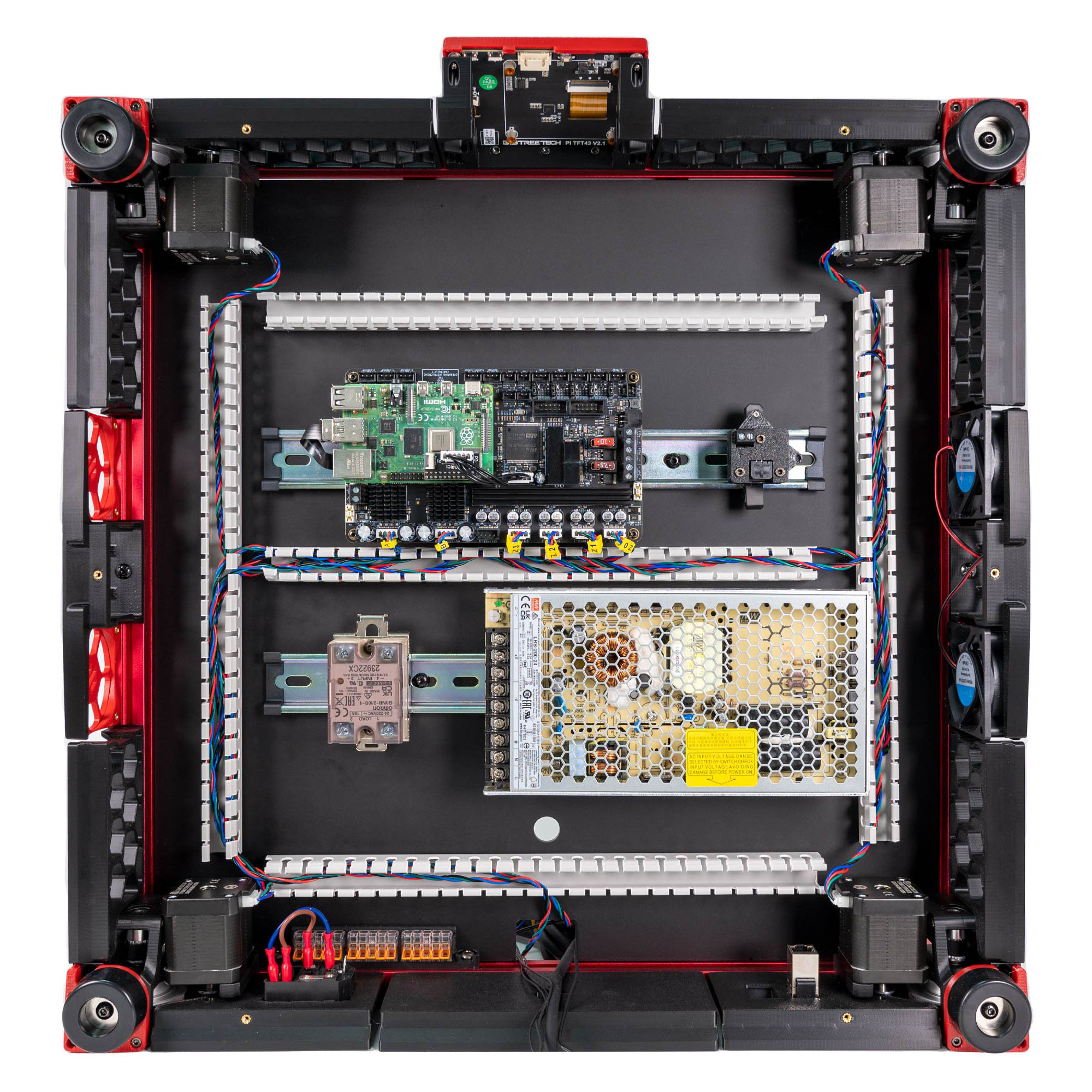 Step 10.41A motor → HV-STEPPER-1
Step 10.42B motor → HV-STEPPER-0
Step 10.43Z0–Z3 → STEPPER-0 to STEPPER-3with a helper
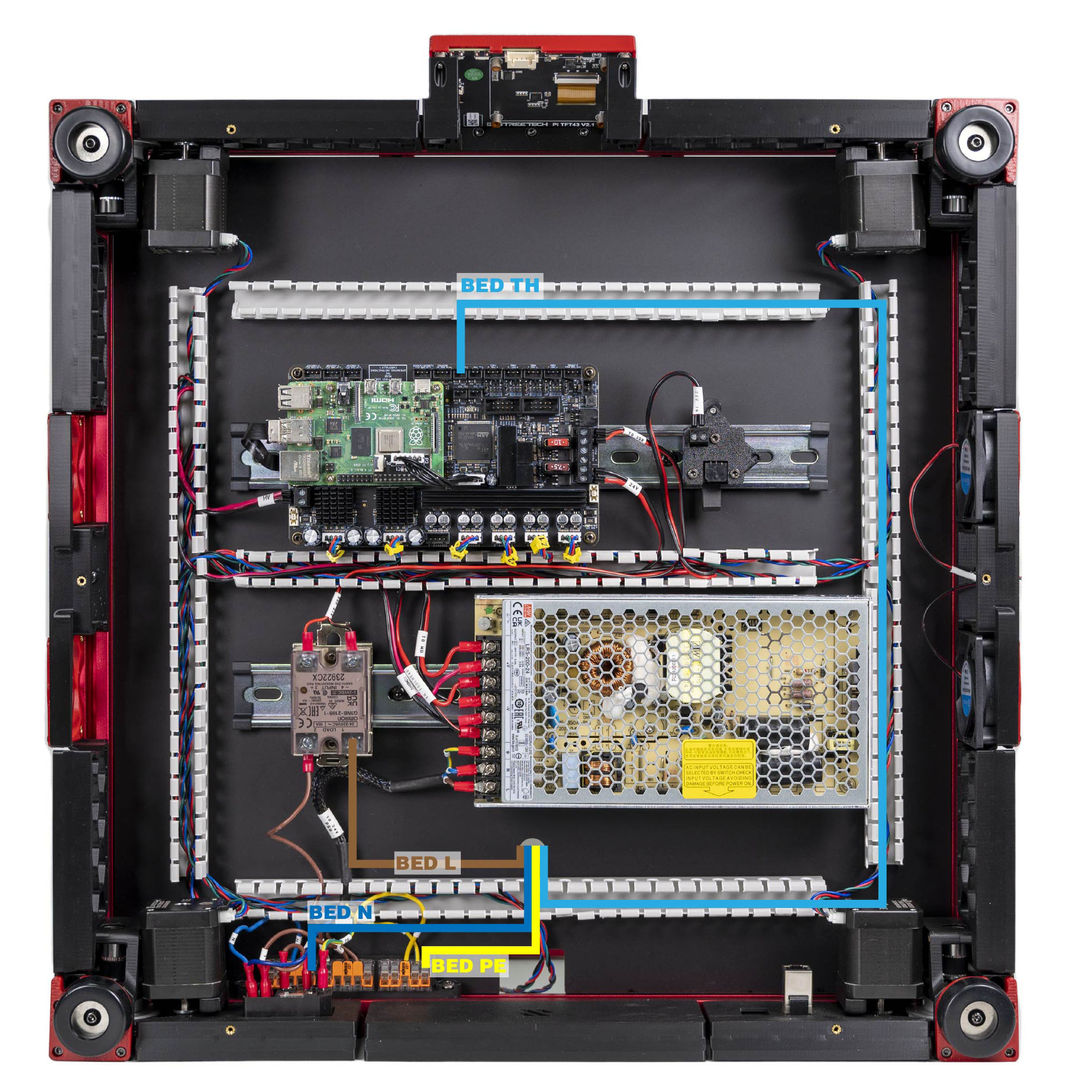 Step 10.44Bed thermistor → TH1
Step 10.45XY endstops → X-ENDSTOP and Y-ENDSTOPwith a helper
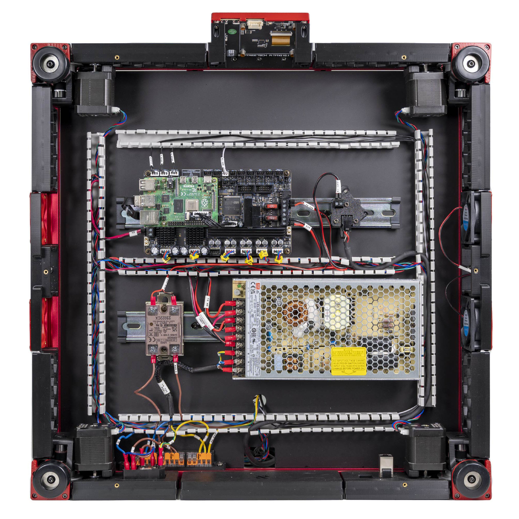 Step 10.46Nozzle probe → Z-ENDSTOP
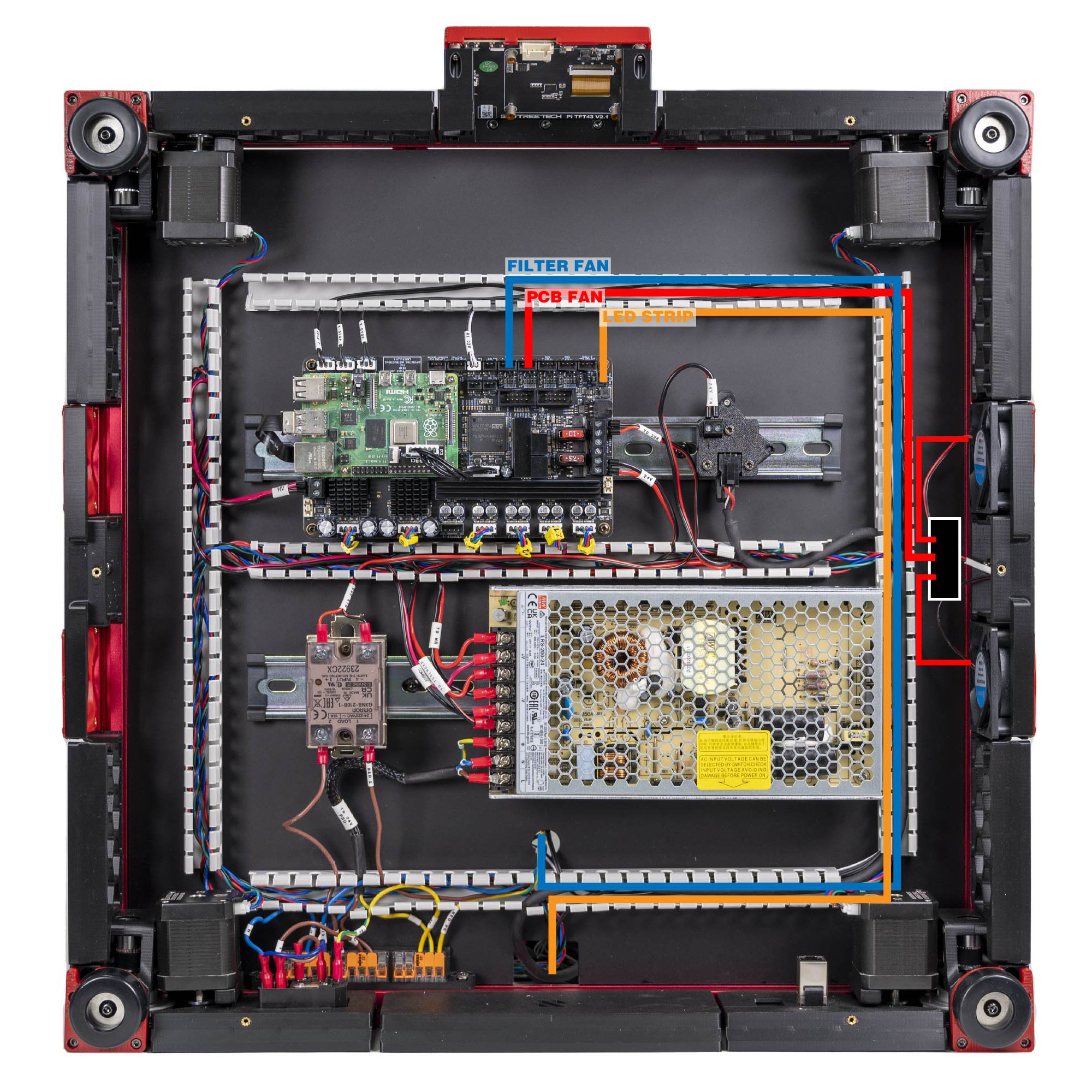 Step 10.47Electronics-bay fan pair → FAN2
Step 10.49LED strip → LED-Strip
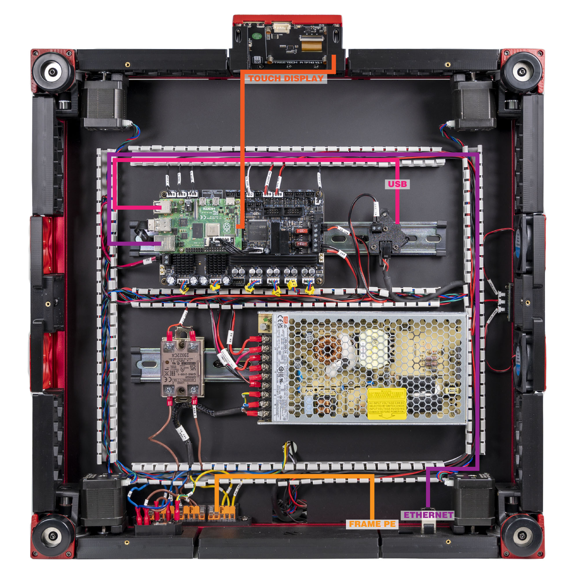 Step 10.50DSI ribbon: Raspberry Pi ↔ touchscreen
 Step 10.51Ethernet: Raspberry Pi ↔ rear keystone
Step 10.52USB: Raspberry Pi ↔ Leviathan
Step 10.53USB: Raspberry Pi ↔ USB adapter PCB
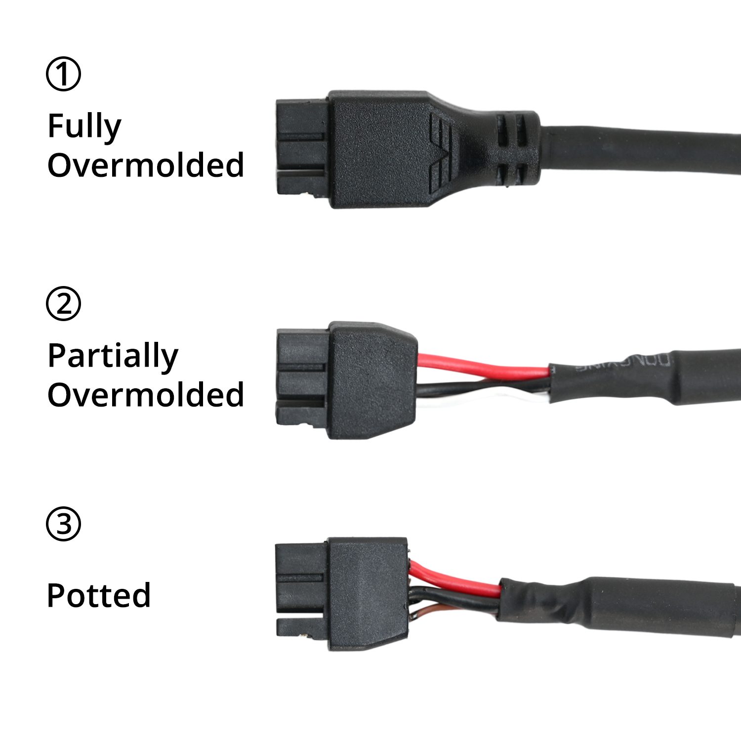 Step 10.54Identify your umbilical and its two connectors
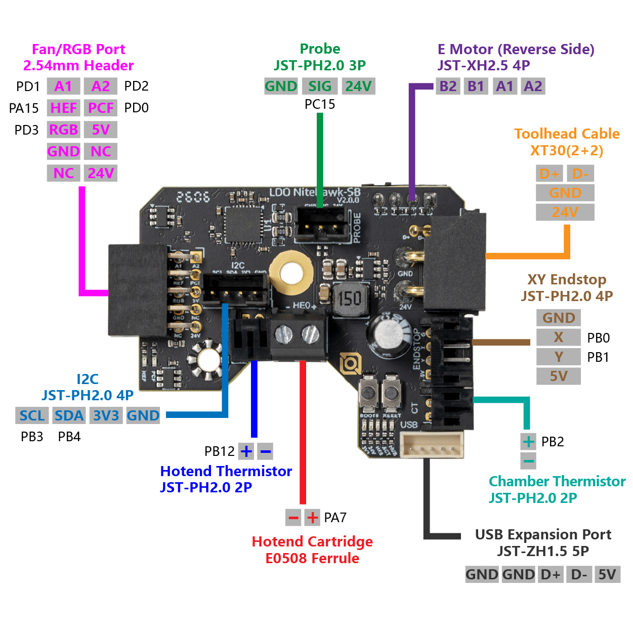 Step 10.55Connector types on the V2 toolboard
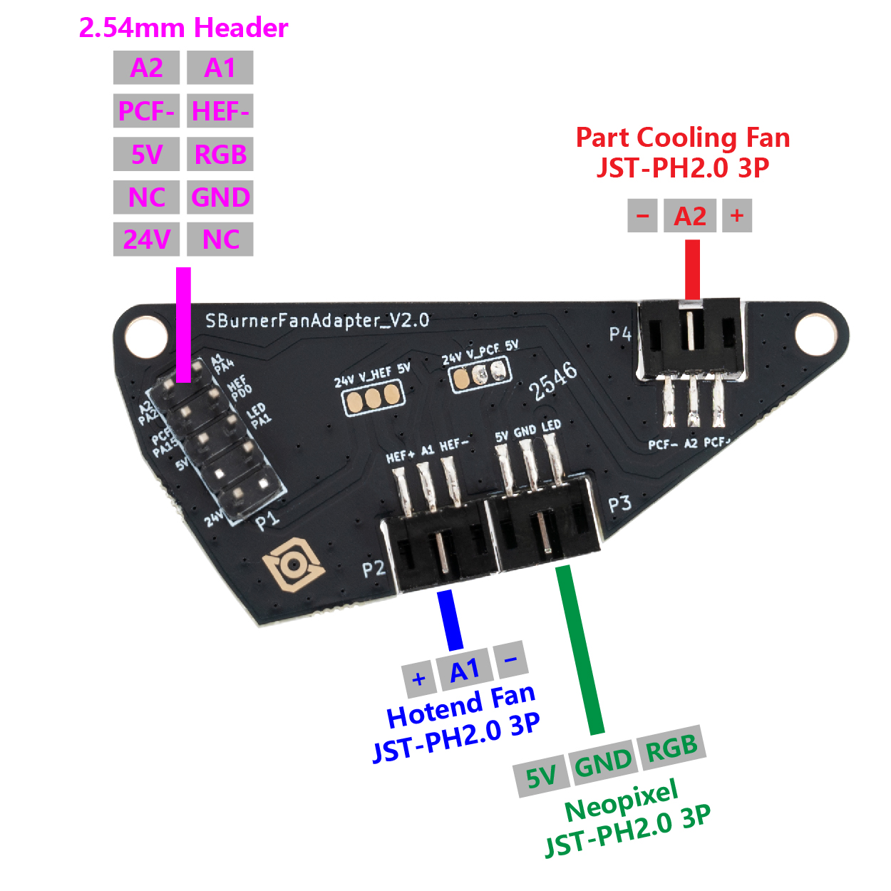 Step 10.56The fan-adapter header is keyed and reversed
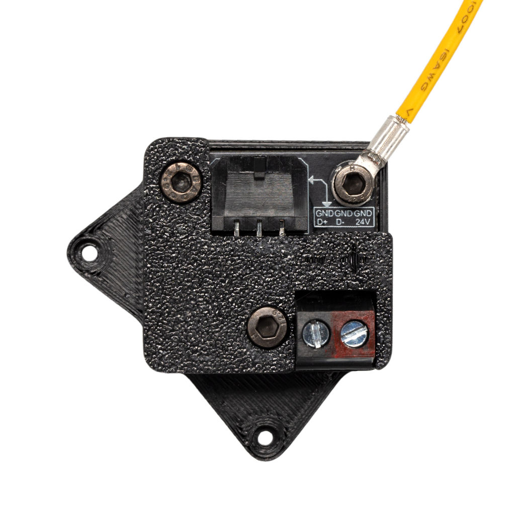 Step 10.57The USB adapter cover is the partial cover
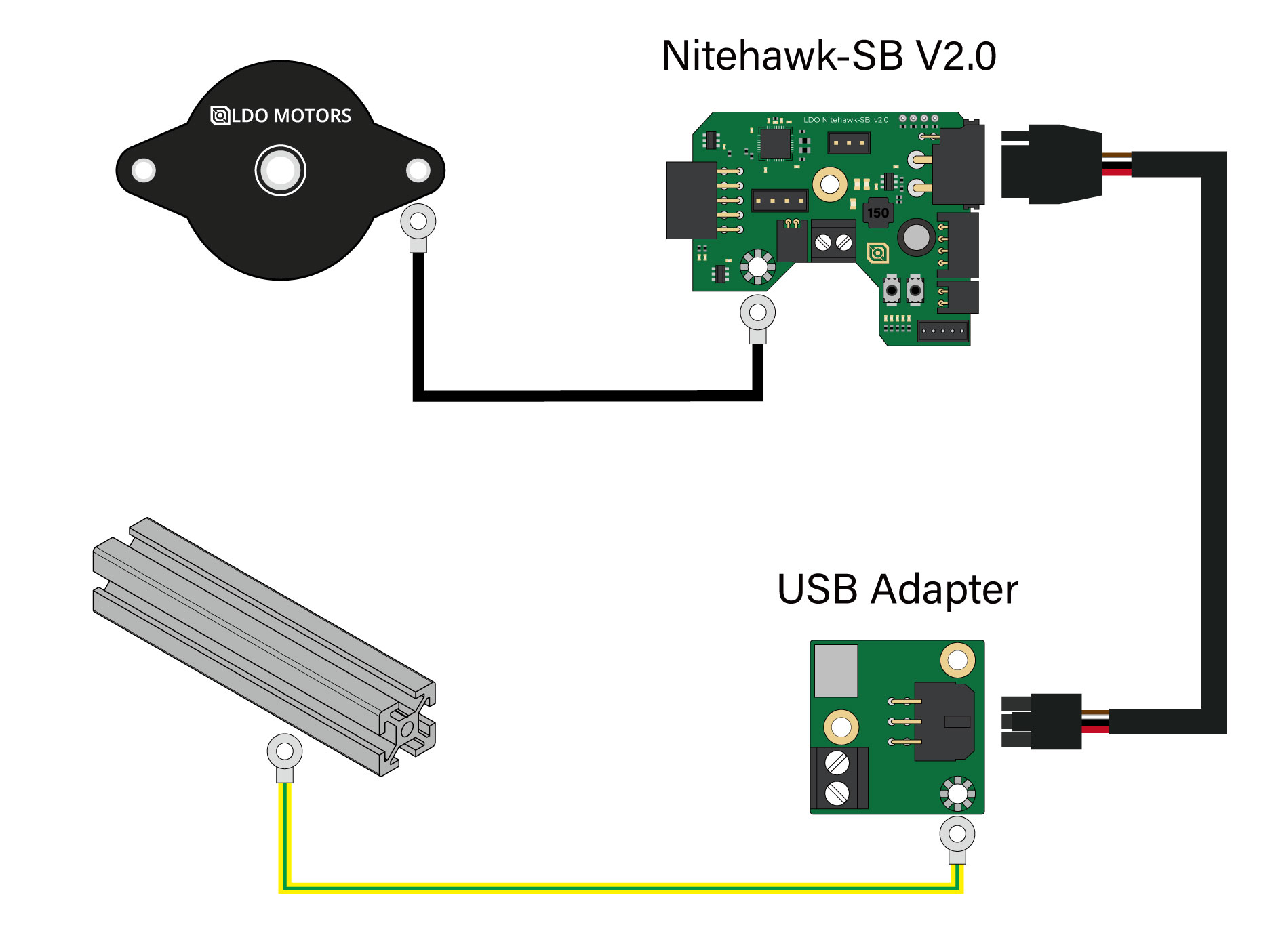 Step 10.58Fit the ESD grounding path
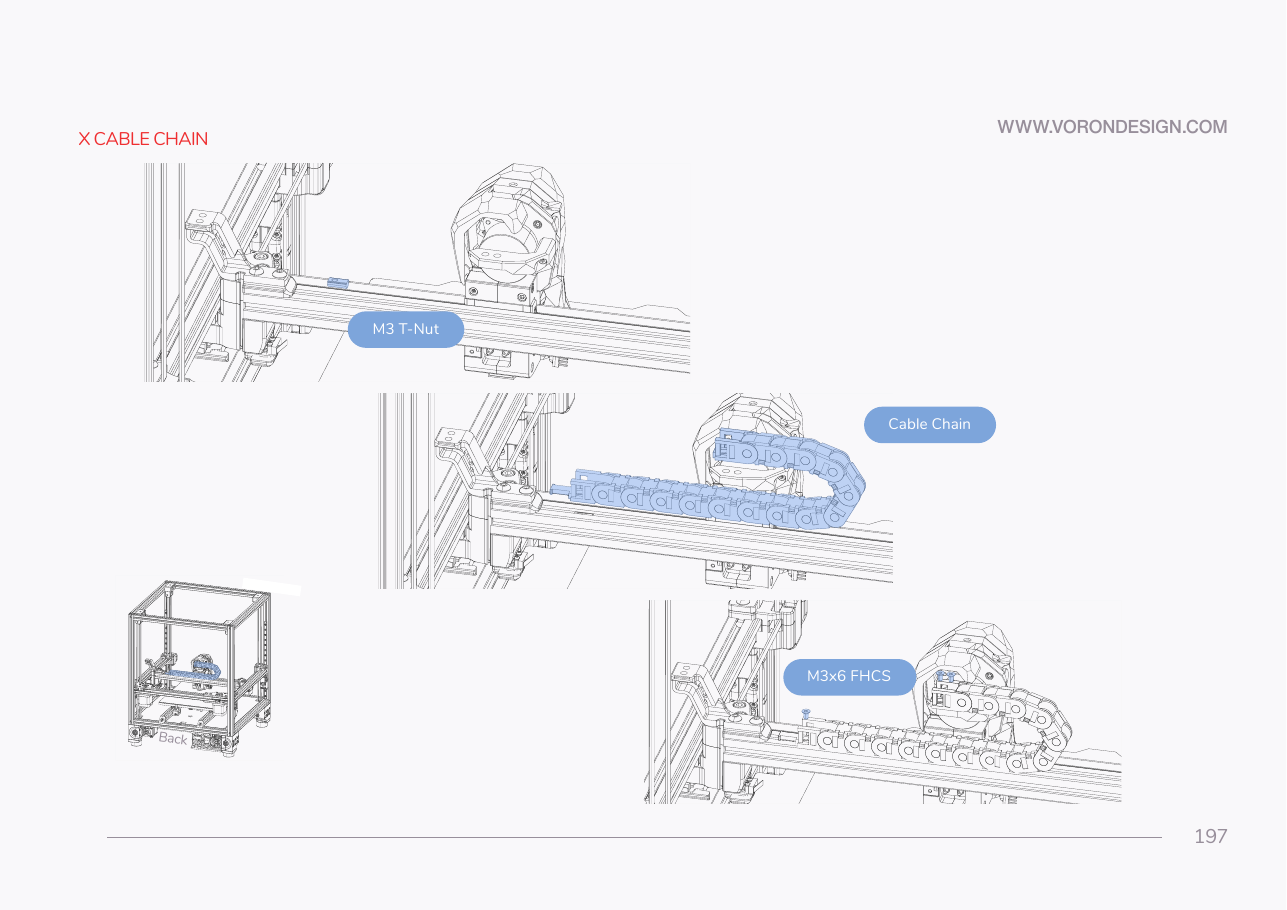 Step 10.59Fit the X drag chain
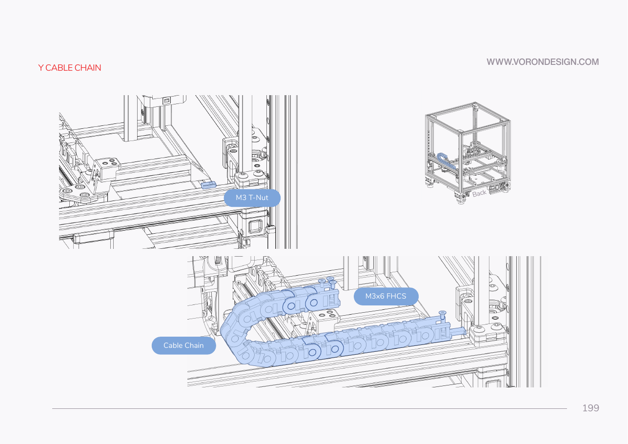 Step 10.60Fit the Y drag chain
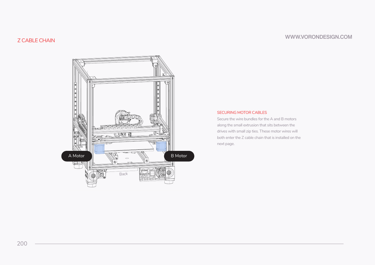 Step 10.61Secure the A and B motor cables
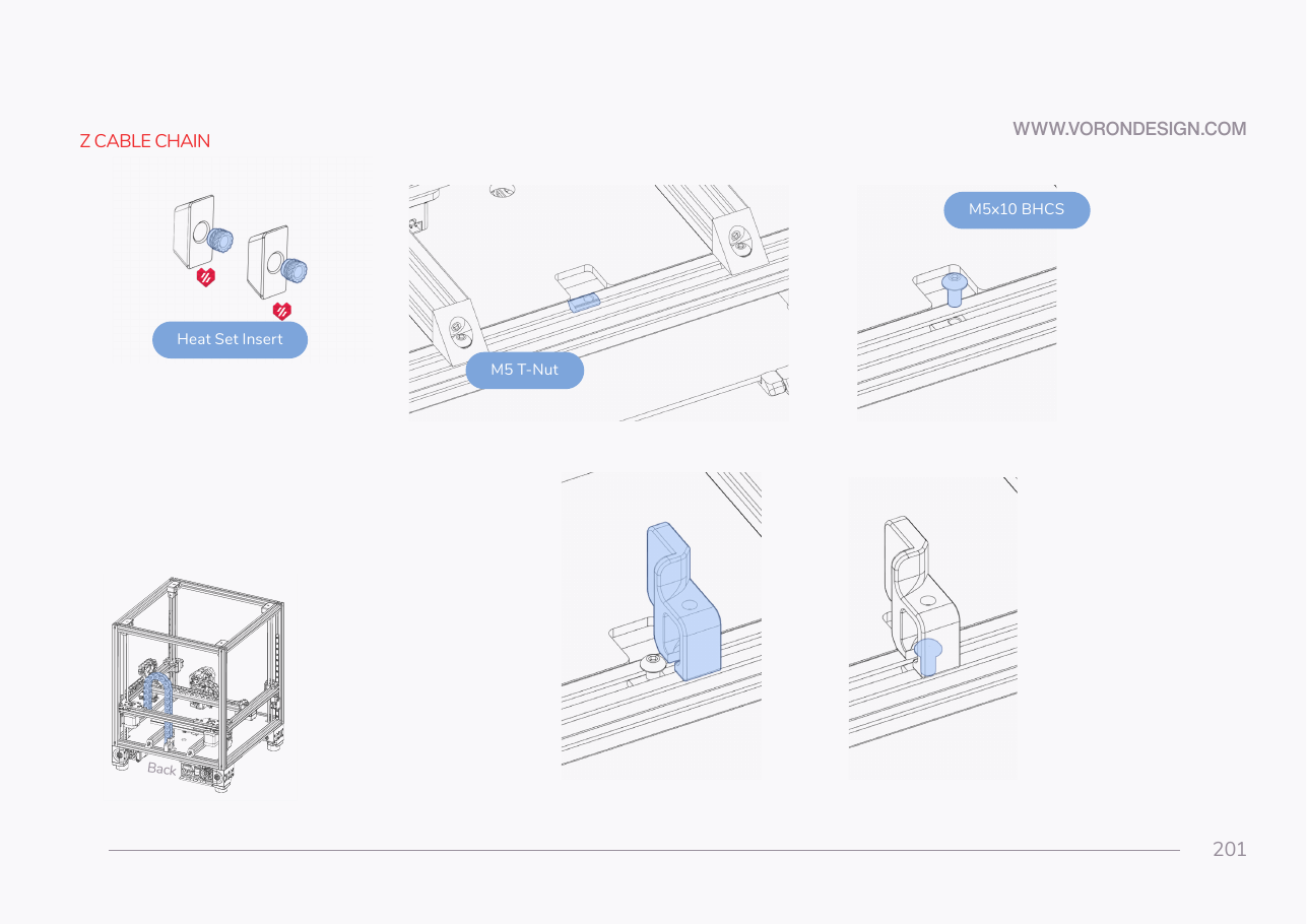 Step 10.62Fit the Z chain guide and the Z chain
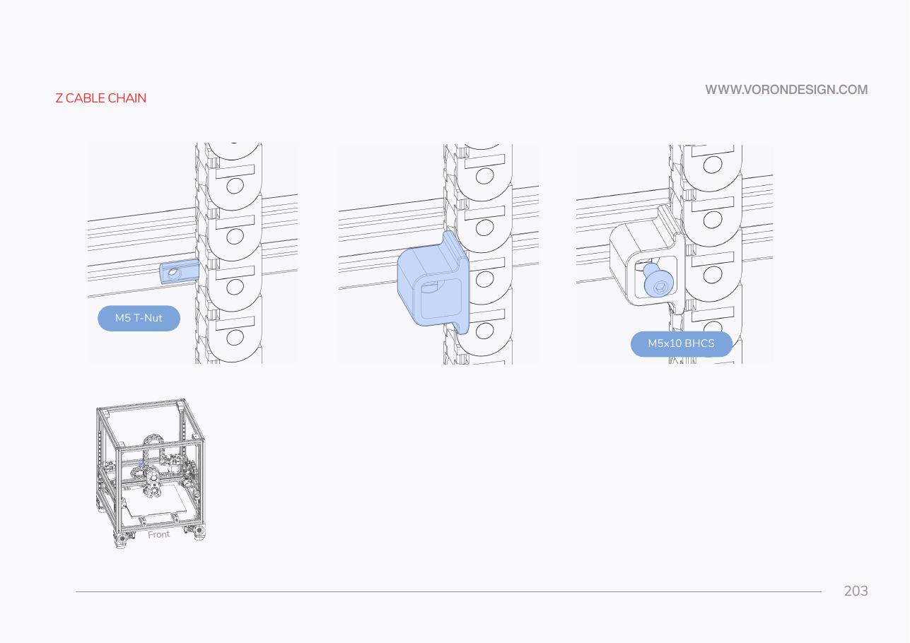 Step 10.63Fit the Z chain bottom anchor
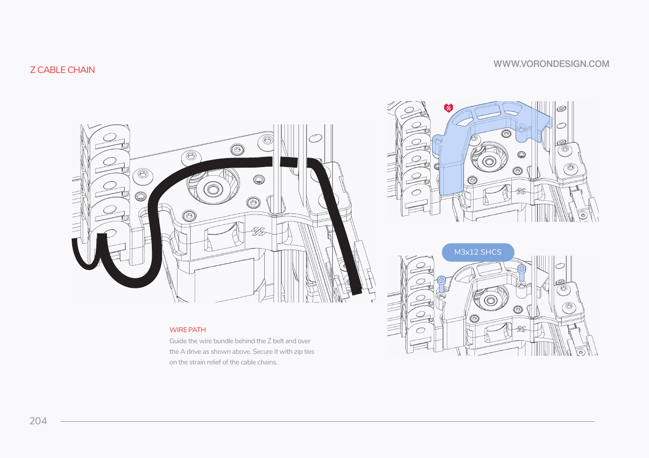 Step 10.64Fit the Z chain retainer bracket and set the wire path
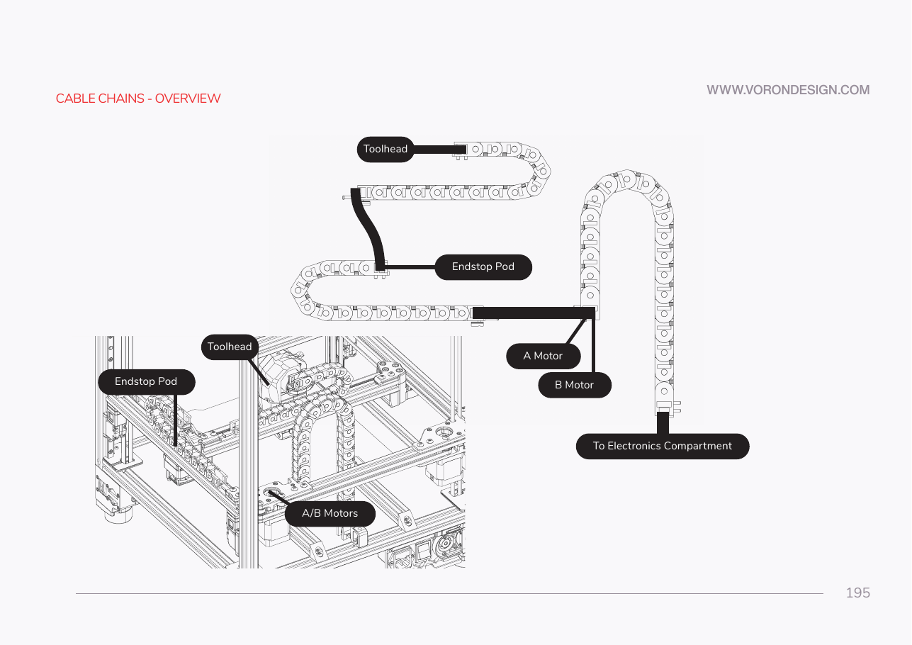 Step 10.65Lay the harness into the chainswith a helper
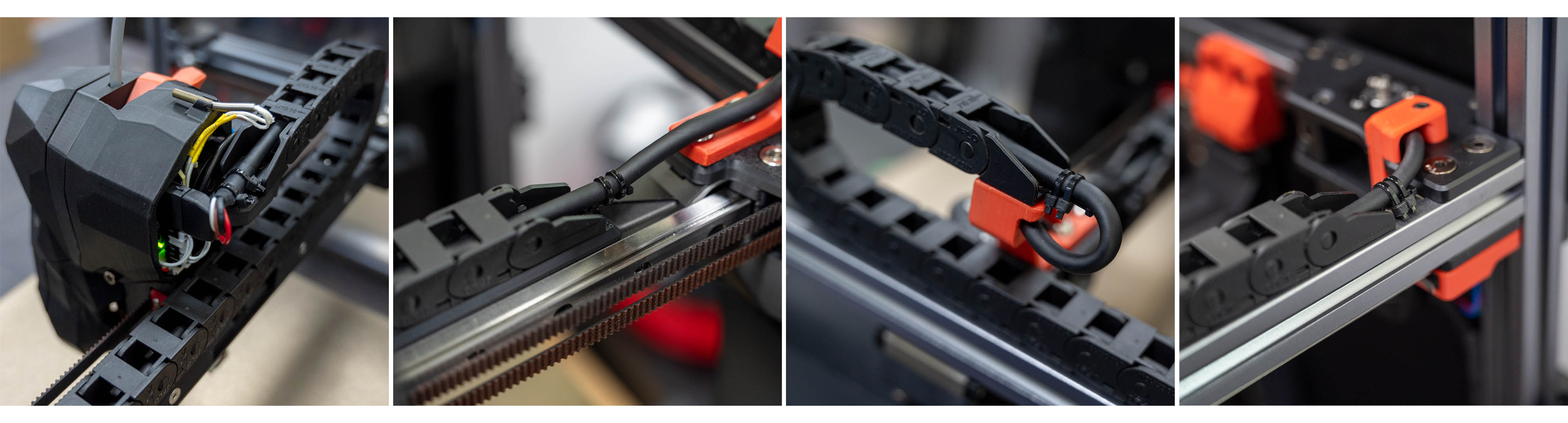 Step 10.66Zip-tie both ends of every chain
Step 10.67Umbilical → USB adapter PCB
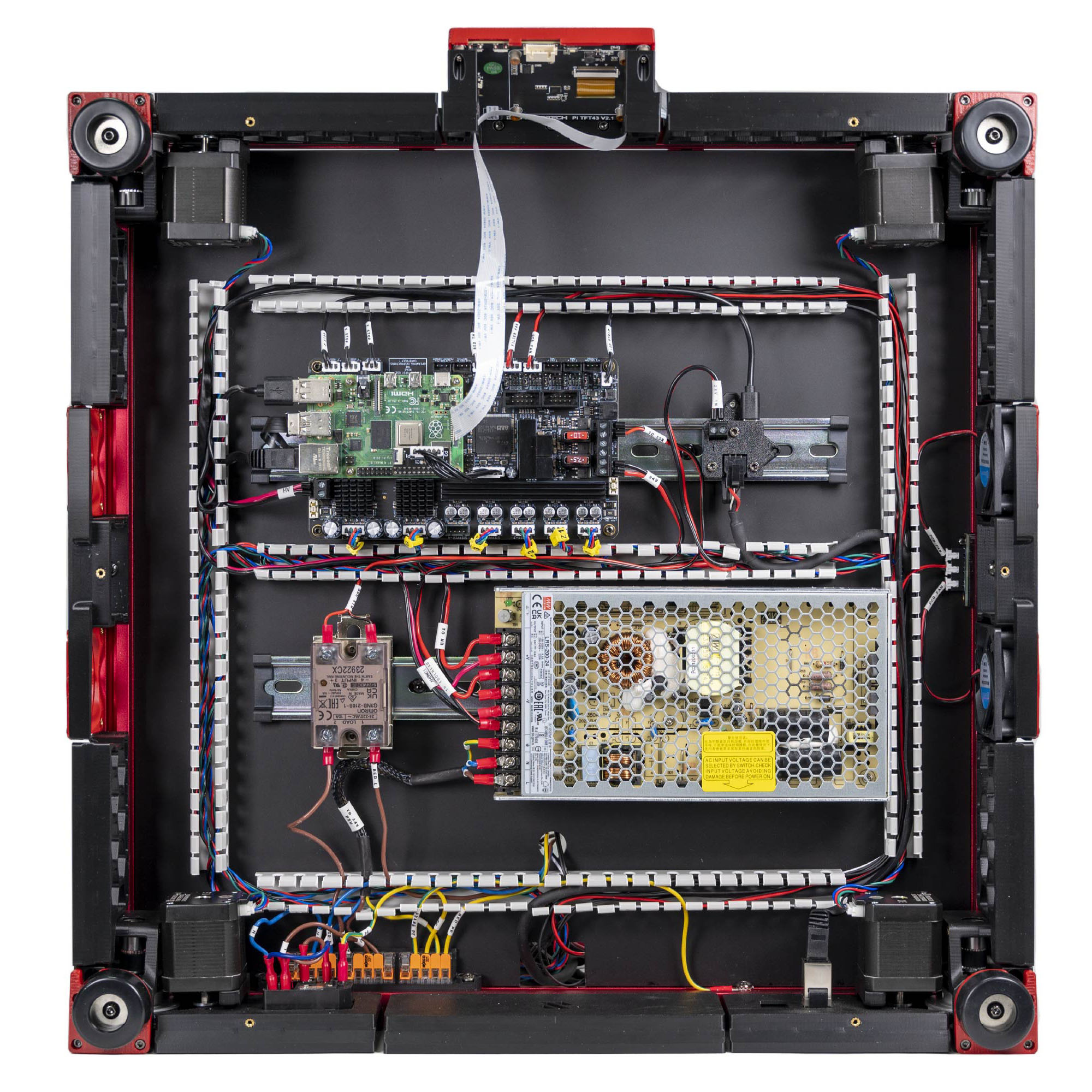
Step 10.68Dress the below-deck runs into the ducts
Step 10.69Strain-relieve the deck opening
Step 10.70Tag every cable at the board endwith a helper
Step 10.71Leave the duct covers off
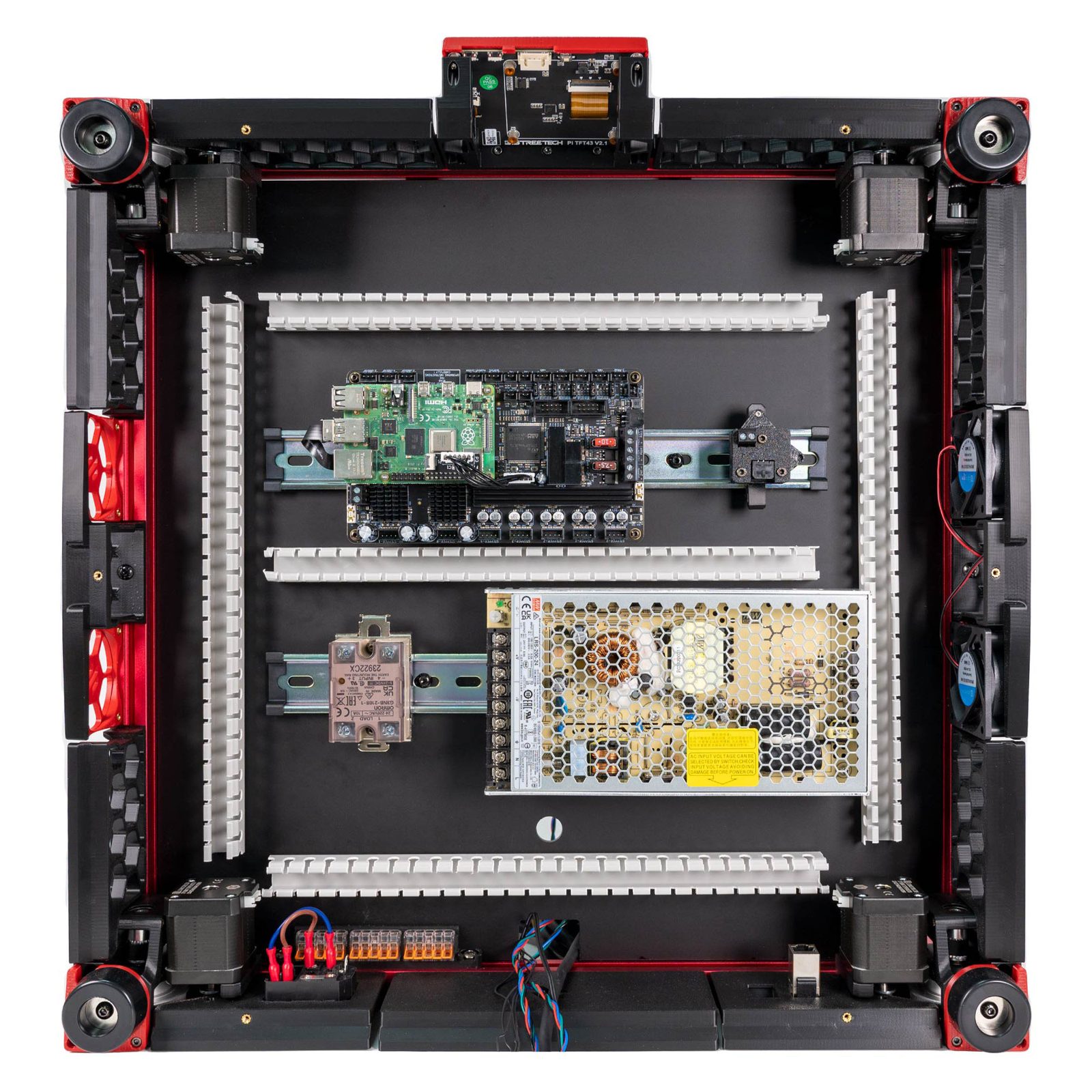
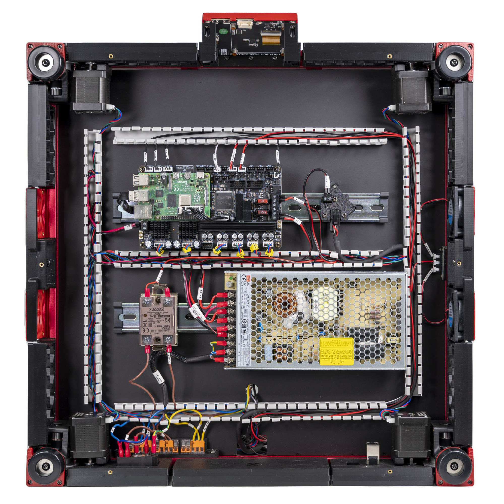
Step 10.72Walk the bay against LDO's finished photowith a helper
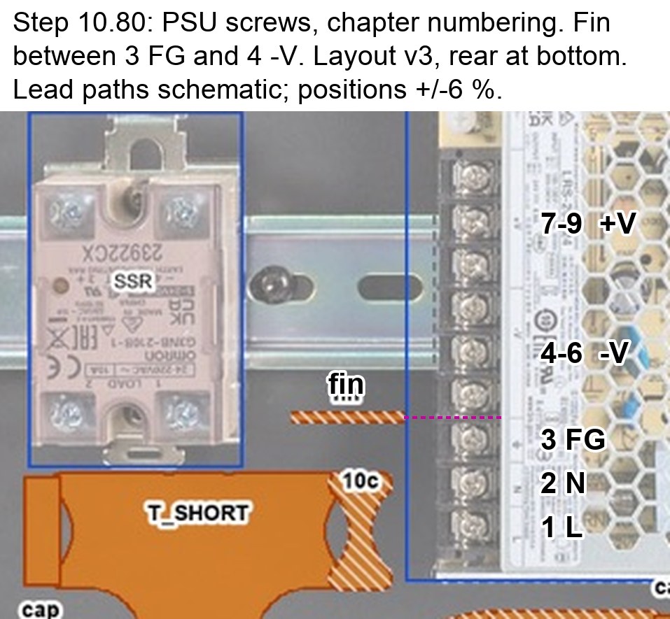 Step 10.80Fit the strip fin and close the AC lids
Step 10.7424 V railswith a helper
Step 10.755 V railwith a helper
Step 10.76Thermistors at room temperaturewith a helper
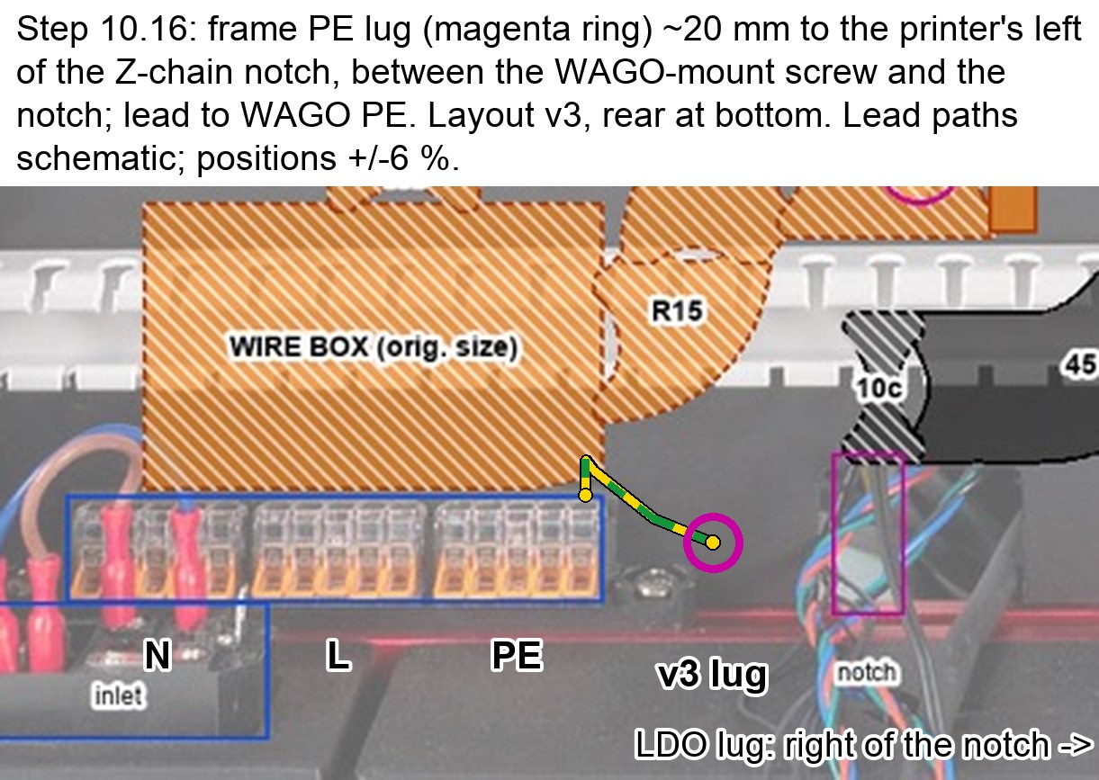 Step 10.77Protective-earth bondingwith a helper
Step 10.78SSR polarity and isolation, one last timewith a helper
Gather per session — what to lay out before each bench segment.
- Steps 10.1–10.4 · ~15 min — Already on the bench: the Meanwell PSU; the Leviathan mainboard
- Steps 10.5–10.9 · ~30 min — The Cable Kit box: PSU AC cable set, 3 cores ×1 · Tools and consumables: multimeter; label maker; PH2 screwdriver · Already on the bench: the AC inlet module; the three WAGO 221-415 blocks in their mount; the inlet module's three pre-wired cores; WAGO N, L and PE
- Steps 10.10–10.16 · ~30 min — Fasteners, Tools & Misc box: M5 locking washer ×2; M5×10 BHCS (verify on bench) ×1; M5 roll-in T-nut (verify on bench) ×1 · The Cable Kit box: SSR to Wago cable ×1; Bed L extension lead ×1; Bed N extension lead ×1; FRAME PE cable ×1 · Tools and consumables: multimeter · Already on the bench: the Omron SSR on its DIN bracket; the plate's Bed L, Bed N and BED TH leads and its PE ring terminal; the bed WAGO mount with its two WAGO 221-412 and the 2×2 XH splicer; the Bed L and Bed N extension leads, far ends still free; the Bed L extension lead; the Bed N extension lead; the bed PE lead
- Steps 10.17–10.23 · ~25 min — Other box: C13 power cord ×1 · Tools and consumables: multimeter
- Steps 10.24–10.29 · ~25 min — The Cable Kit box: 24V PSU to MB cable ×1; HV to MB HV cable ×1; 24V power cable ×1; SSR to MB cable ×1 · Tools and consumables: multimeter; cable tag · Already on the bench: two of the jumpers bagged in Ch 09
- Steps 10.30–10.34 · ~25 min — The Cable Kit box: XY endstop cable ×1; Z endstop cable ×1 · Tools and consumables: tweezers or the supplied 2.5 mm flat screwdriver · Already on the bench: the XY endstop PCB on the right XY joint; the nozzle-probe PCB
- Steps 10.35–10.39 · ~35 min — Electronics 2 box: 3×2 XH splicer PCB ×1;
2x3 Splitter Spacer(LDO-supplied printed) ×1 · Fasteners, Tools & Misc box: M3×5×4 heat-set insert (verify on bench) ×20; M3×6 FHCS ×16; M3×8 SHCS ×18; M3 hammerhead T-nut ×18 · The Cable Kit box: LED STRIP cable ×1 · The LDO kit, box not in the Rev D BOM: COB LED strip ×2 · Printed parts:cob_light_strip_mount_100mm×6 (bin 10-lights);cob_light_strip_mount_50mm×2 (bin 10-lights) · Tools and consumables: extrusion slot cover, 6 mm, up to 9 · Set out for later steps:z_chain_guide×1 (bin 10-chains);[a]_z_chain_retainer_bracket×1 (bin 10-chains) · Already on the bench: the eight assembled COB mounts; the chamber thermistor, if your batch has one - Steps 10.40–10.46 · ~30 min — The Cable Kit box: Bed TH cable ×1 · Tools and consumables: cable tag ×7 · Already on the bench: the A motor's lead; the B motor's lead; the four Z motor leads; the two 3-pin ends of the XY endstop cable; the Z endstop cable
- Steps 10.47–10.53 · ~40 min — Electronics 1 box: Keystone CAT6 insert ×1 · Electronics 2 box: 3×2 XH splicer PCB ×1;
2x3 Splitter Spacer×1 · Fasteners, Tools & Misc box: M3×8 SHCS ×2; M3 hammerhead T-nut ×2 · Belts, Chains & Fans box: 60×60×20 fan ×2 · The Cable Kit box: PCB FAN cable ×1; FILTER FAN cable ×1; Ethernet patch cable ×1; USB-A to USB-C cable, short (verify on bench) ×1; USB cable ×1 · The display box: FFC ribbon cable (verify on bench) ×1 · Set out for later steps: 4.3" capacitive DSI display ×1;mount.stl×1 (bin 10-tft);[a]_faceplate×1 (bin 10-tft); M3×5×4 heat-set insert ×2; M3×8 SHCS ×2; M2.5×6 screw ×4 · Already on the bench: the LED STRIP cable from the junction PCB - Steps 10.54–10.58 · ~25 min — Fasteners, Tools & Misc box: M3×8 SHCS (verify on bench) ×1; M3 roll-in T-nut (verify on bench) ×1 · Tools and consumables: multimeter · Already on the bench: the toolhead umbilical cable; the fitted
usb_adapter_mount_partial_cover(bin 08-CW2); the long supplied grounding cable, ring already on the USB adapter - Steps 10.59–10.64 · ~35 min — Fasteners, Tools & Misc box: M3 roll-in T-nut ×2; M3×6 FHCS (verify on bench) ×6; M5 roll-in T-nut ×2; M5×10 BHCS ×2; M3×10 FHCS ×4; M3×12 SHCS ×2 · Belts, Chains & Fans box: drag chain 10×10 R18 ×2; drag chain 10×15 R28 ×1 · Printed parts:
z_chain_guide×1 (bin 10-chains);z_chain_bottom_anchor×1 (bin 10-chains);[a]_z_chain_retainer_bracket×1 (bin 10-chains) · Tools and consumables: small zip tie ×4 · Already on the bench: the CW2 chain anchor on the toolhead - Steps 10.65–10.67 · ~25 min — Tools and consumables: 2.5 mm flat screwdriver; zip ties, 12 · Already on the bench: the umbilical; the XY endstop cable; the A and B motor bundles
- Steps 10.68–10.80 · ~30 min — Printed parts:
V2L_STRIP_FIN×1 (bin 10-lids-AC);CMD_V2_6B_WIRE_BOX_COVER×1 (bin 10-lids-AC);V3L_90DEG_R15_COVER×2 (bin 10-lids-AC);V3L_34mm_DUCT_COVER×1 (bin 10-lids-AC);CMD_V2_6B_T_SHORT_COVER×1 (bin 10-lids-AC);V3L_10mm_DUCT_COVER×2 (bin 11-lids-DC, 10-lids-AC) · Tools and consumables: zip ties, 3 to 4; cable tags, for whatever is missing; VHB pad - Steps 10.73–10.79 · ~20 min — Tools and consumables: multimeter; multimeter on Ω; room thermometer