Chapter 02 — Z drives, Z idlers, Z rails, deck panel
Start the chapter · Resume · Read the whole chapter on one page
Before — end of Ch 01: the squared frame
After — end of Ch 02: Z drives, idlers, rails and deck
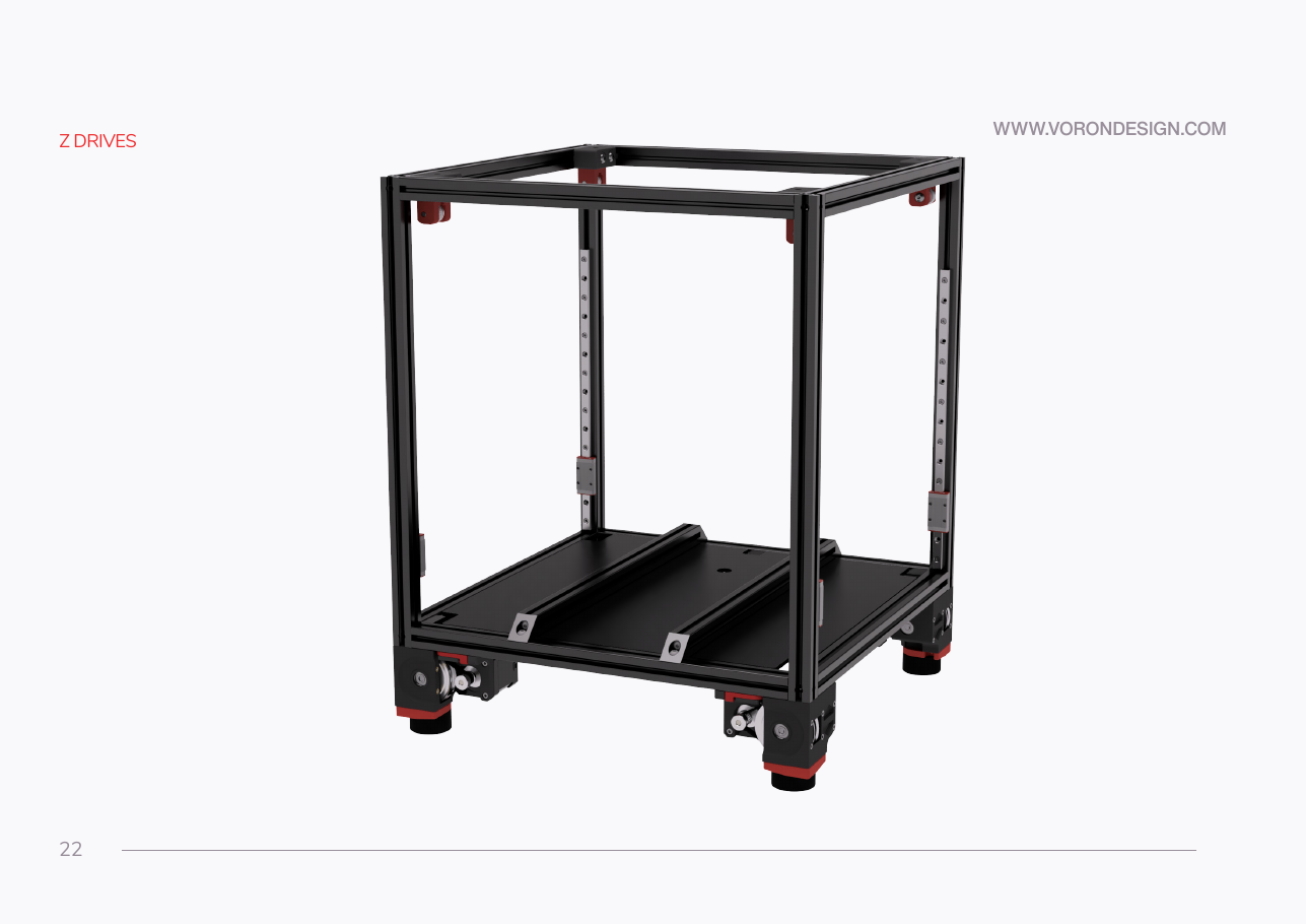 Step 02.01Lay out and label the chapter's printed partswith a helper
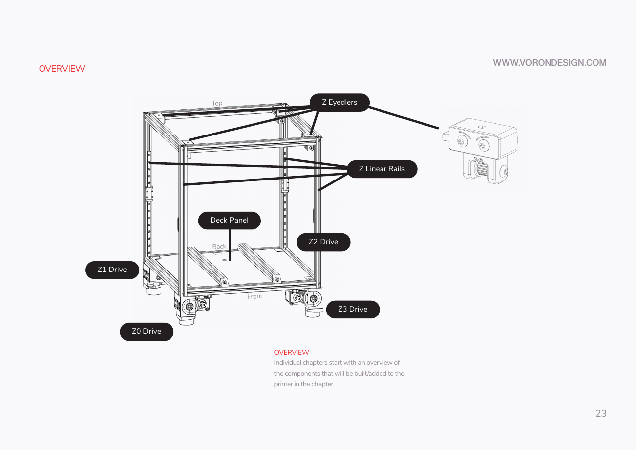 Step 02.02Learn the four Z positions before you build anythingwith a helper
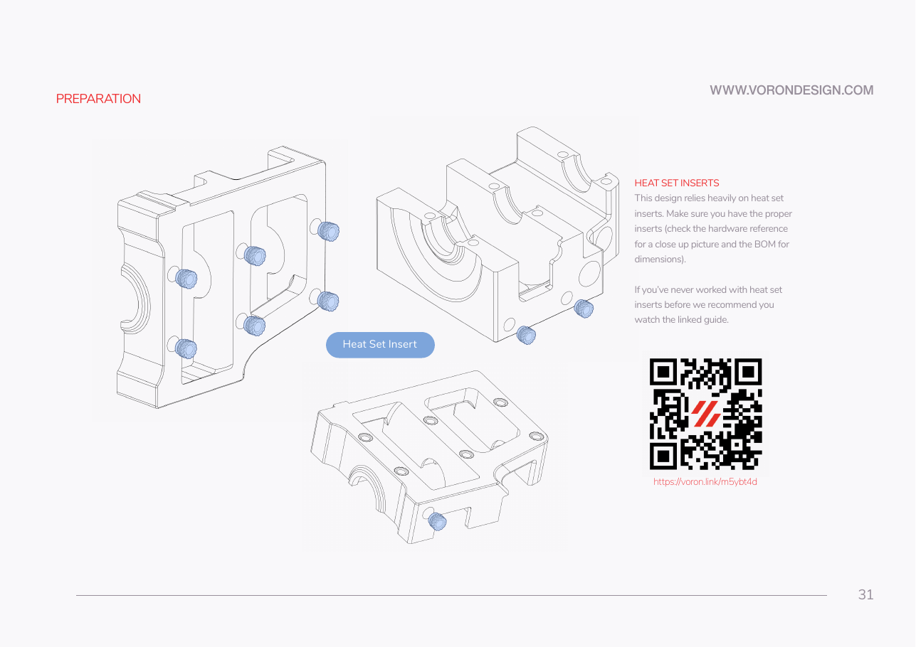 Step 02.03Re-check the iron with the LDO tip on the first insert
Step 02.04Seat the heat-set inserts in the Z drive parts
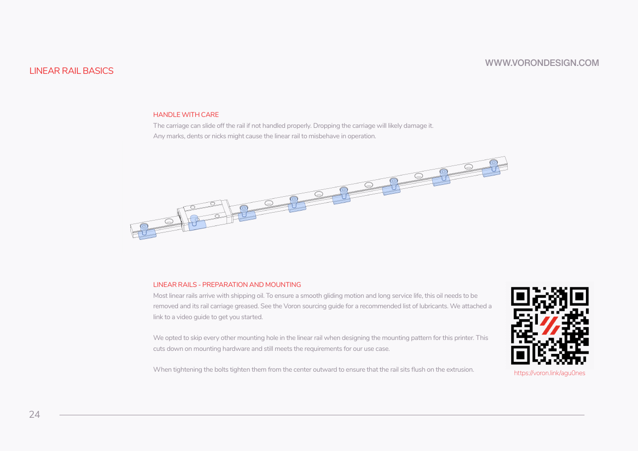 Step 02.05Confirm the four Z rails are already cleaned and greasedwith a helper
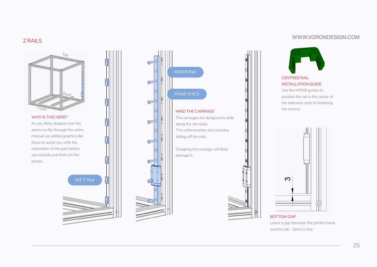 Step 02.06Fit the first Z rail, centred, with the MGN9 guides
Step 02.07Tighten from the centre outward
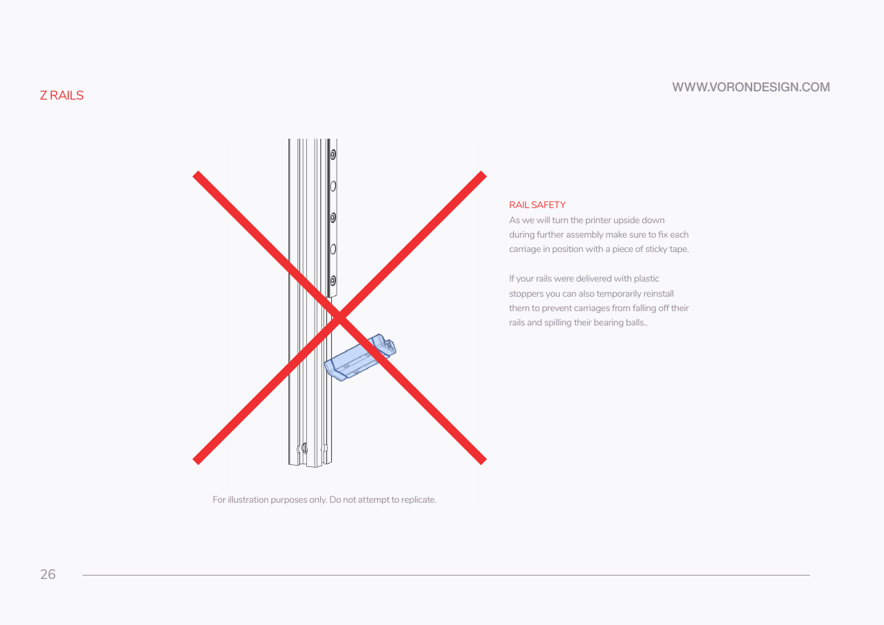 Step 02.08Secure the carriage before the printer is turned over
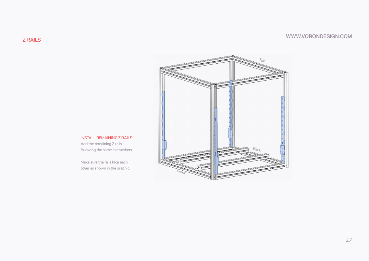 Step 02.09Install the remaining three Z railswith a helper
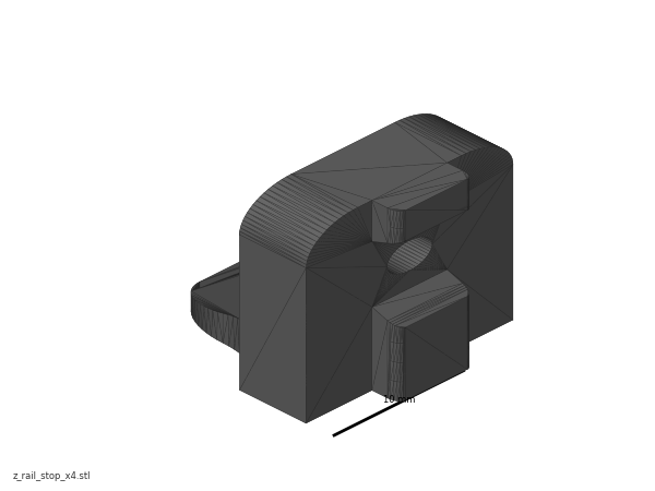 Step 02.10Optional: fit the LDO rail stops at the top of each Z rail
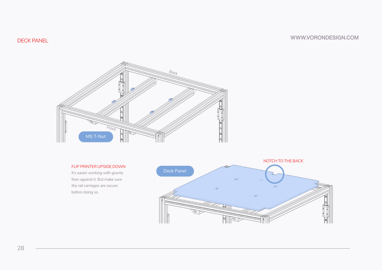 Step 02.11Turn the printer upside down and pre-load the deck T-nutswith a helper
Step 02.12Caliper the deck panel and choose the support thicknesswith a helper
Step 02.13Drop the deck panel in, notch to the backwith a helper
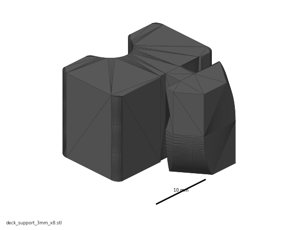 Step 02.14Fit the deck support clips
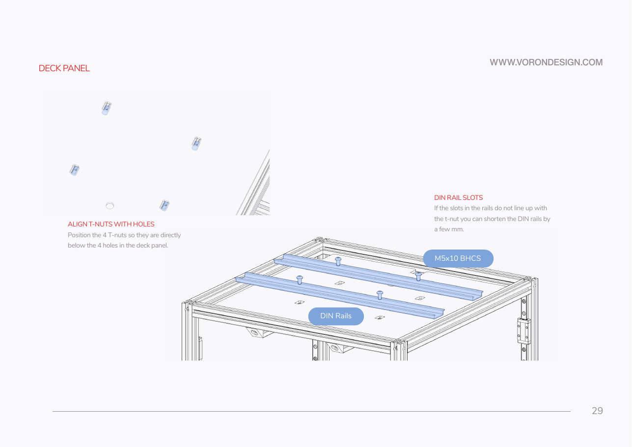 Step 02.15Line the four M5 T-nuts up under the deck holes and stop there
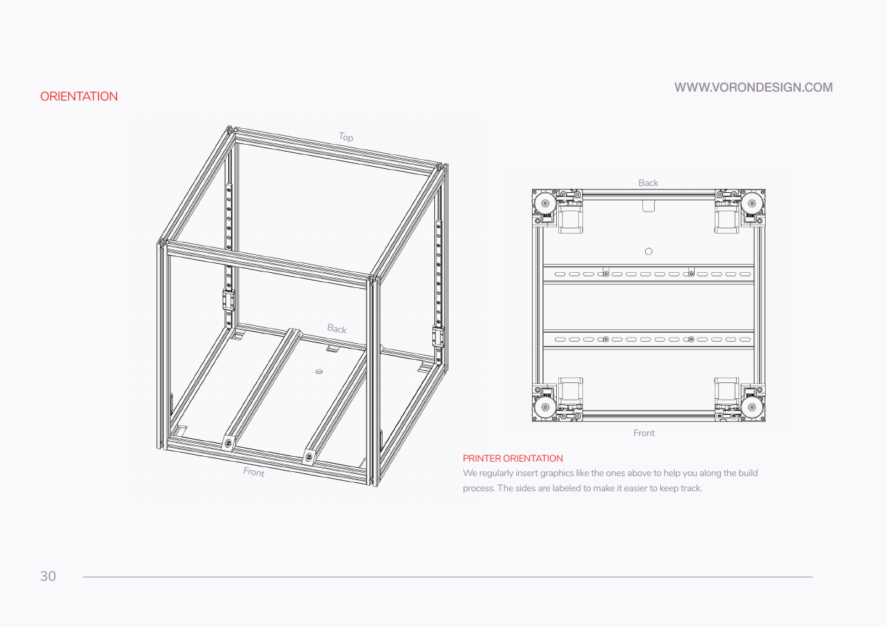 Step 02.16Fix the printer's orientation in your headwith a helper
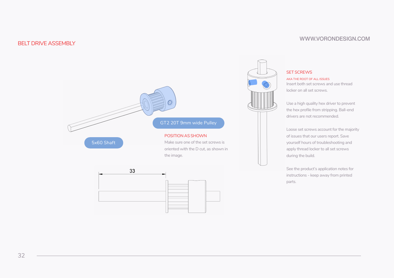 Step 02.17Fit the 20T pulley to the 5×60 shaft, 33 mm outwith a helper
Step 02.18Verify the pulley at 33 mm, then repeat ×4with a helper
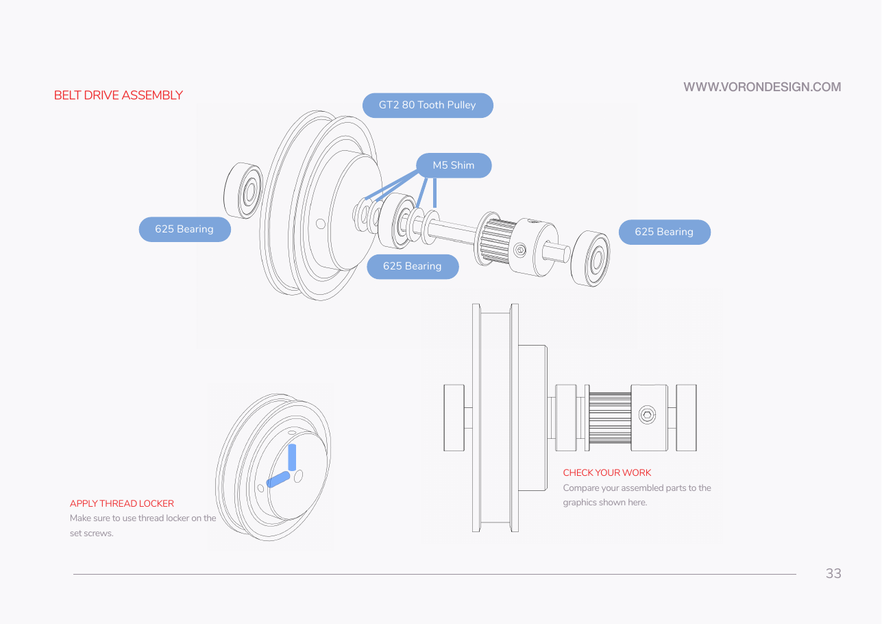 Step 02.19Build the bearing/pulley stack on each shaft
Step 02.20Threadlock the 80T pulley set screws and check your work
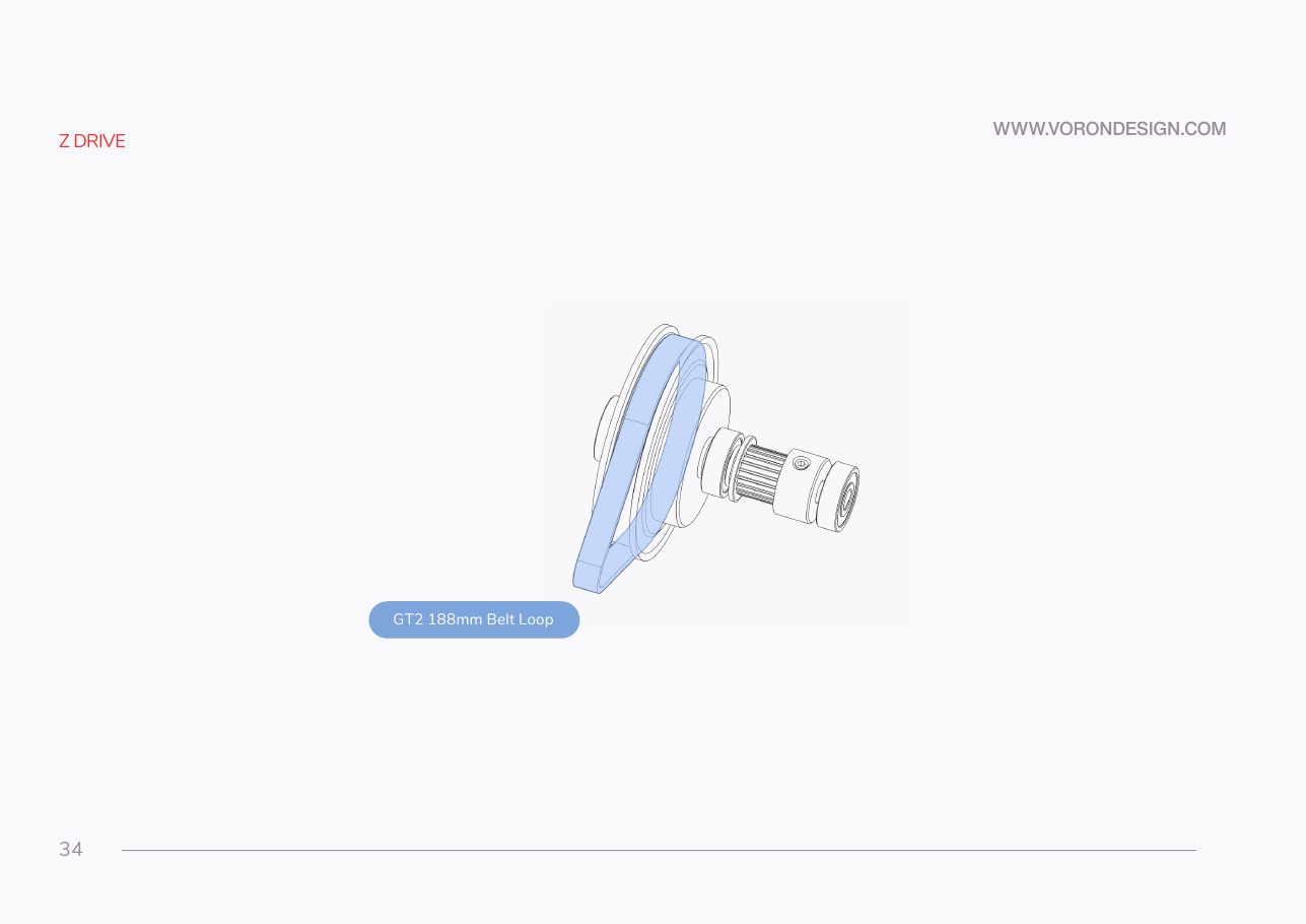 Step 02.21Fit the 188 mm closed belt loop over the 80T pulley
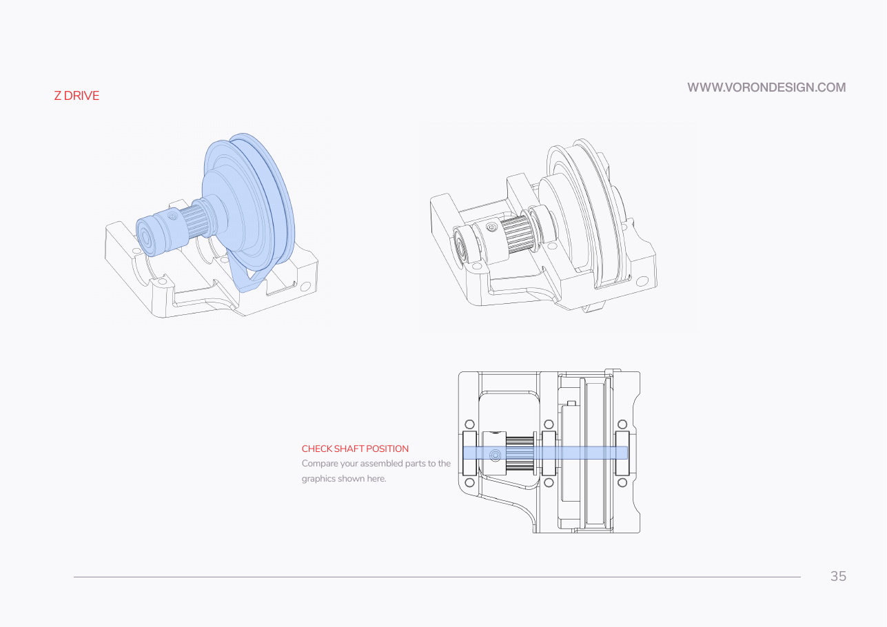 Step 02.22Seat the shaft assembly into z_drive_retainer (the shallow half)
Step 02.23Check the shaft position against the section viewwith a helper
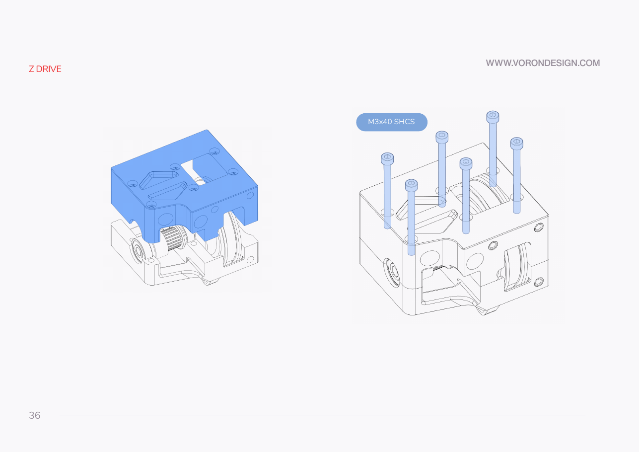 Step 02.24Close the drive with z_drive_main and six M3×40
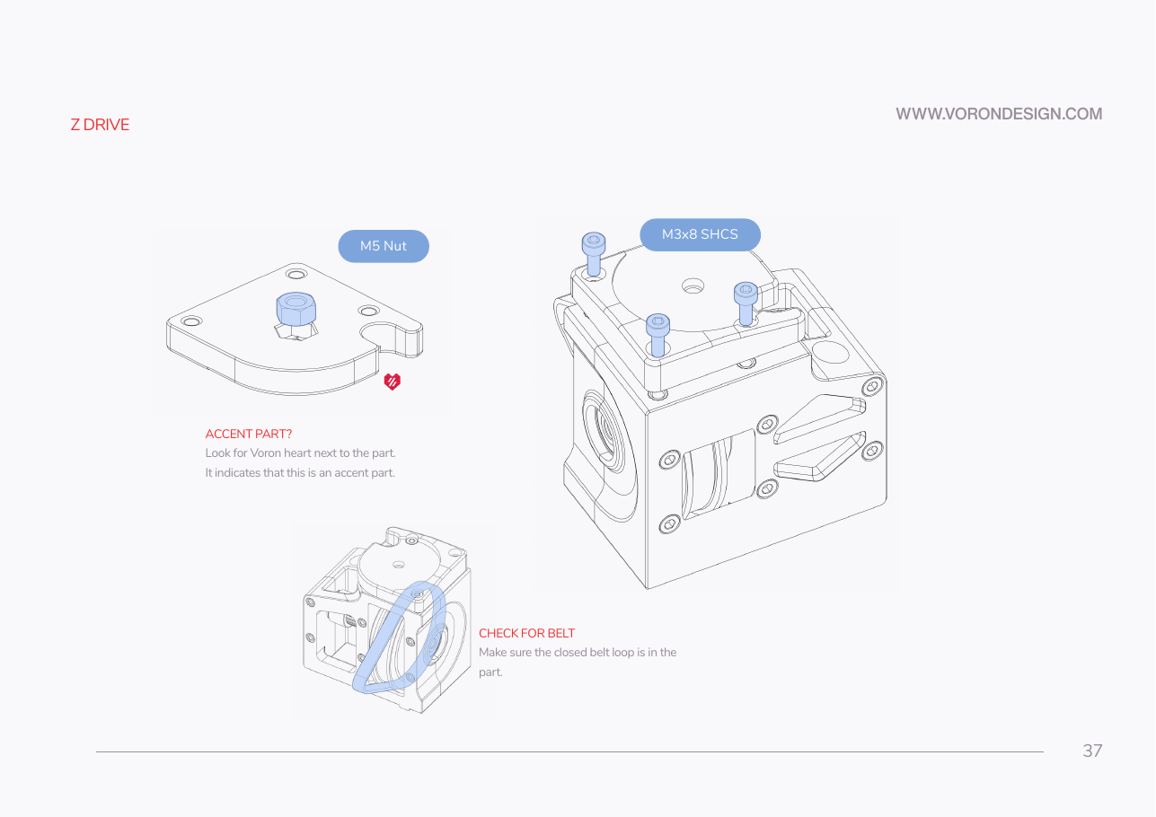 Step 02.25Fit the blue baseplate and its captive M5 nut
Step 02.26Confirm the belt loop is captured
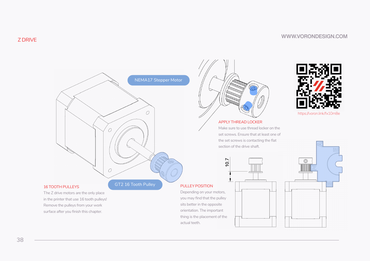 Step 02.27Fit the 16T pulley to a Z motor at 10.7 mmwith a helper
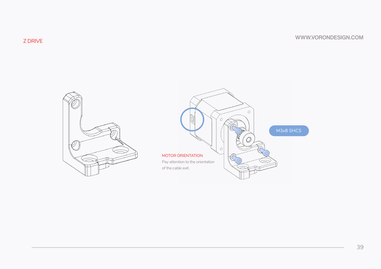 Step 02.28Bolt the motor to z_motor_mount, watching the cable exit
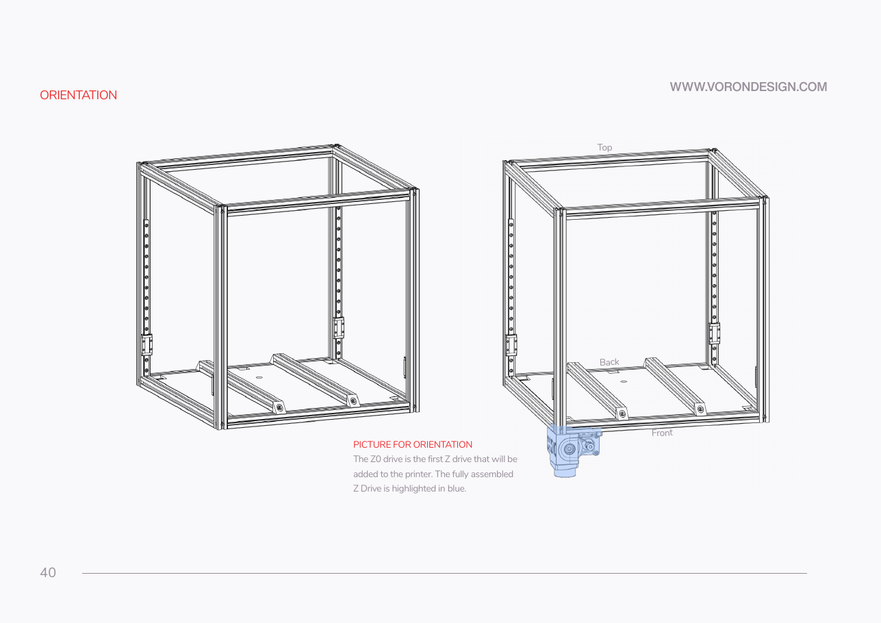 Step 02.29Identify Z0 and start there
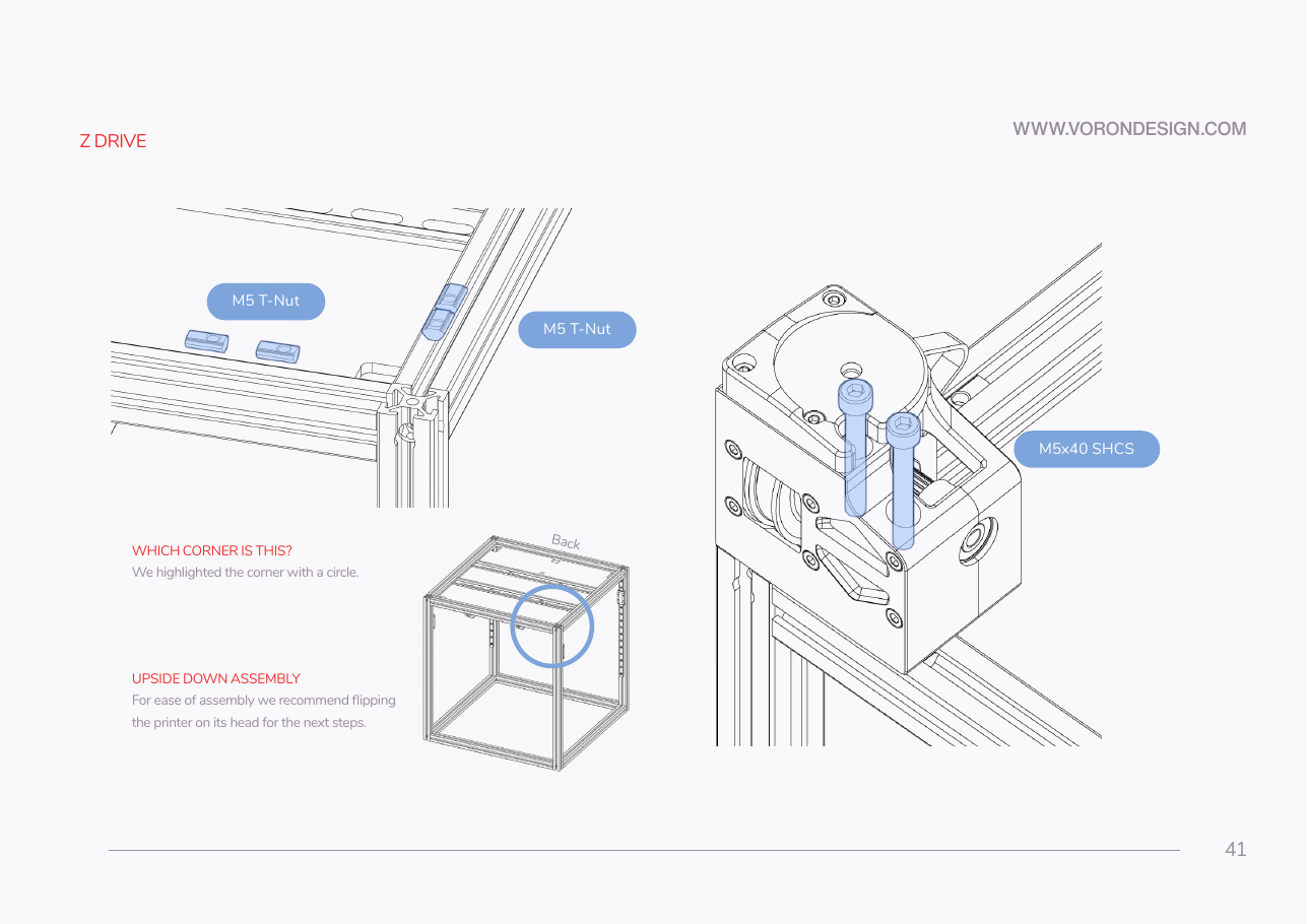 Step 02.30Pre-load four M5 T-nuts at the Z0 corner
Step 02.31Bolt the drive body down with two M5×40
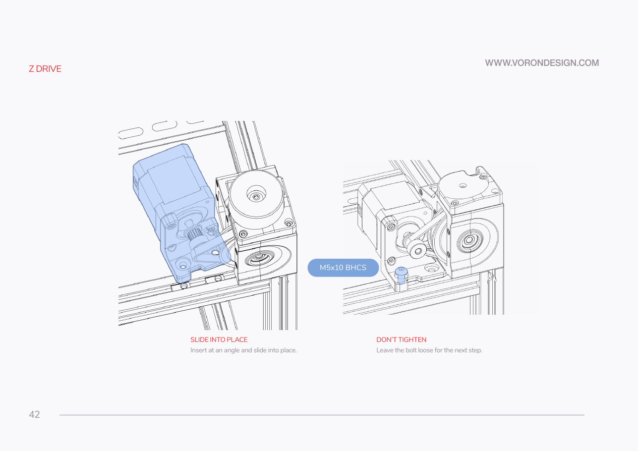 Step 02.32Slide the motor assembly in at an angle
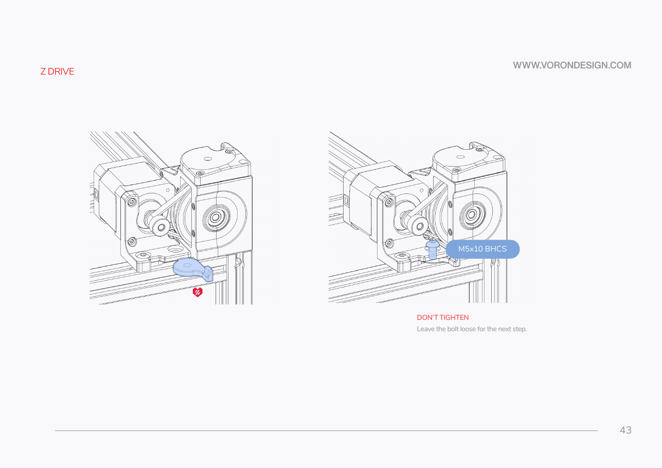 Step 02.33Fit the blue belt tensioner, still loose
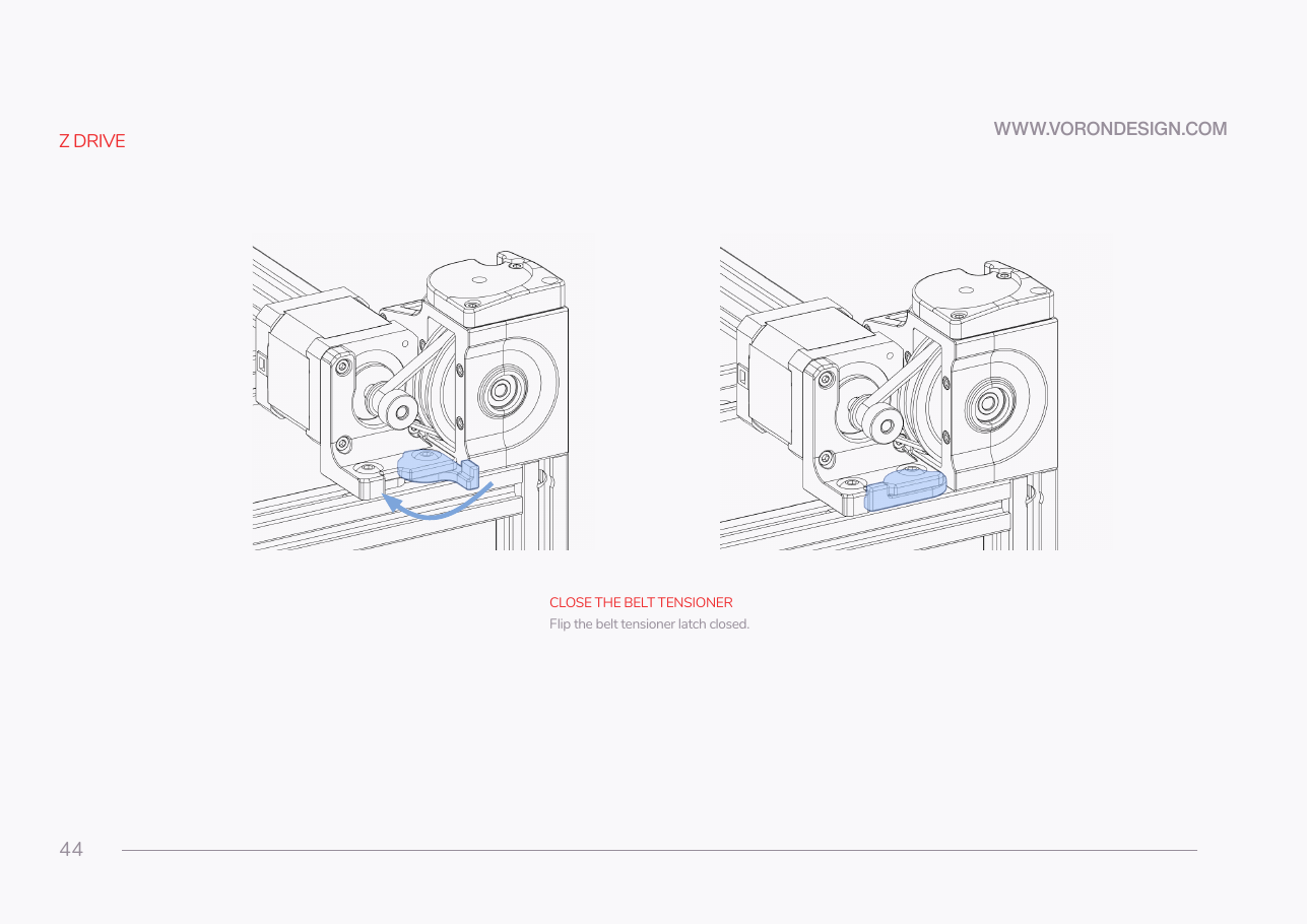 Step 02.34Flip the tensioner latch closed
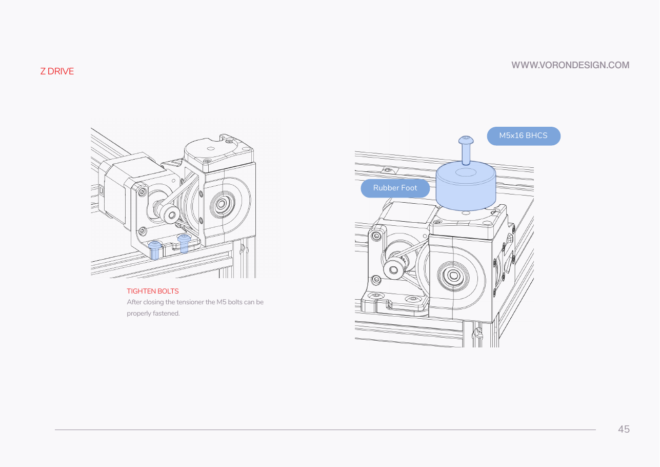 Step 02.35Tighten the M5 bolts
Step 02.36Fit the rubber footwith a helper
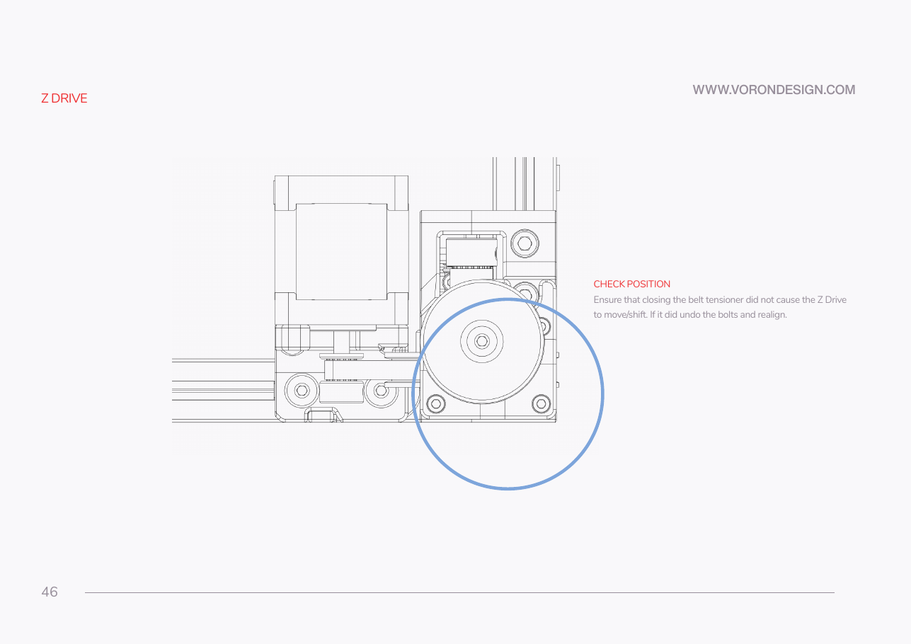 Step 02.37Check the drive did not shift when the tensioner closed
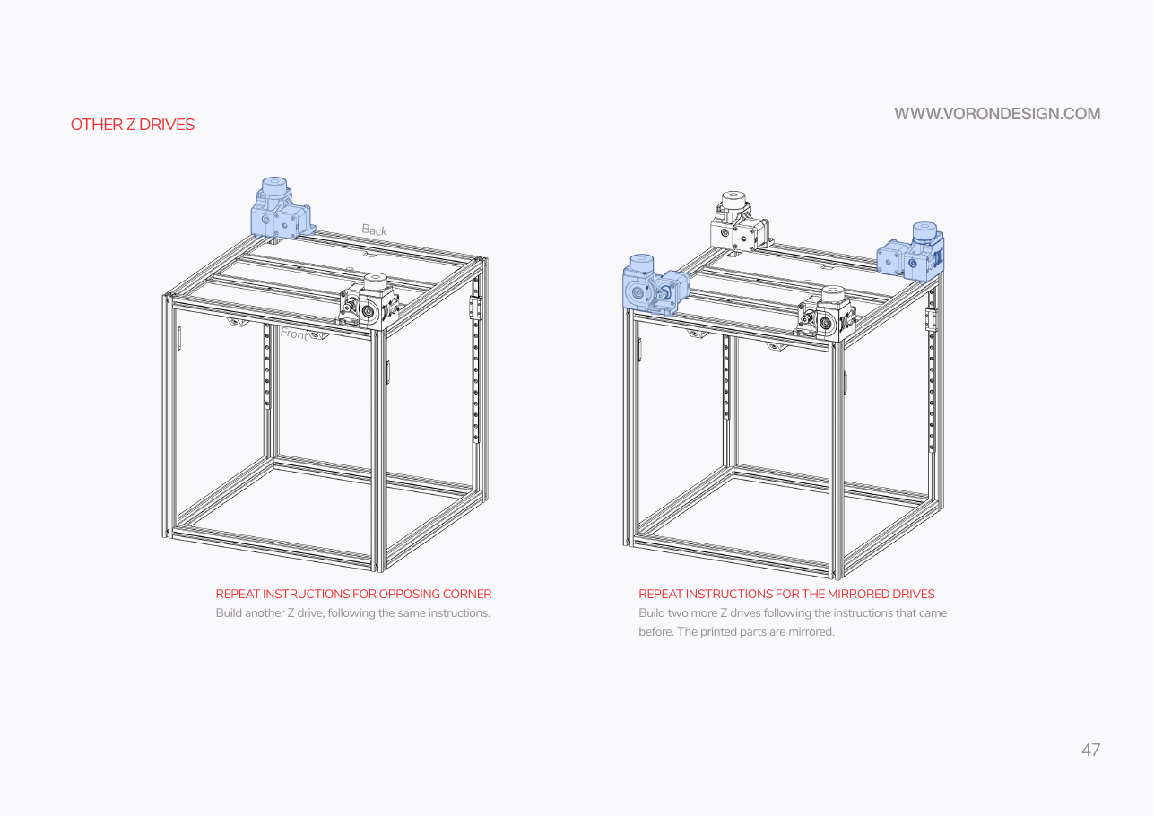 Step 02.38Build and fit the other three Z driveswith a helper
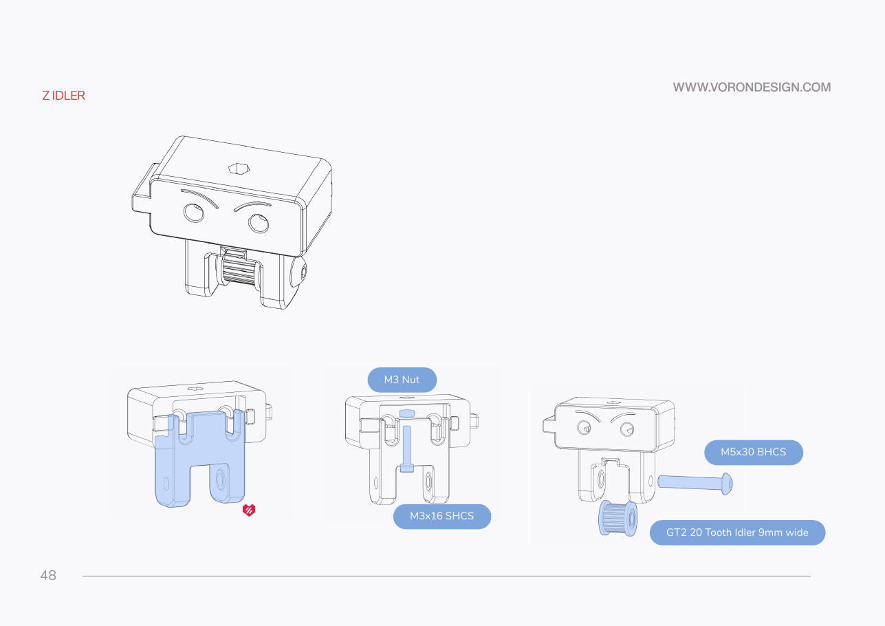 Step 02.39Assemble a Z idler cage
Step 02.40Fit the 20T idler on its M5×30 axle
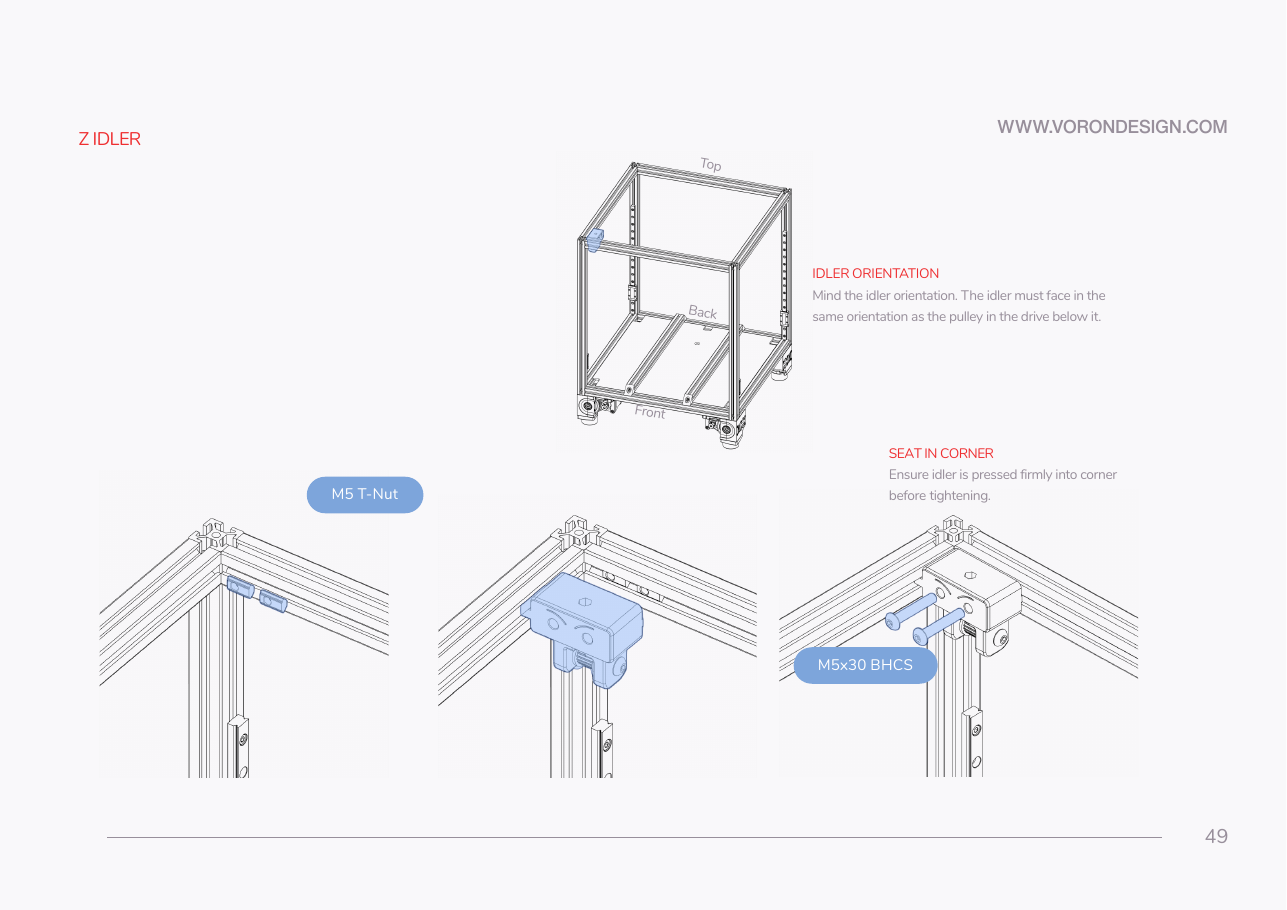 Step 02.41Pre-load two M5 T-nuts at a top corner
Step 02.42Mount the idler, matching the drive below itwith a helper
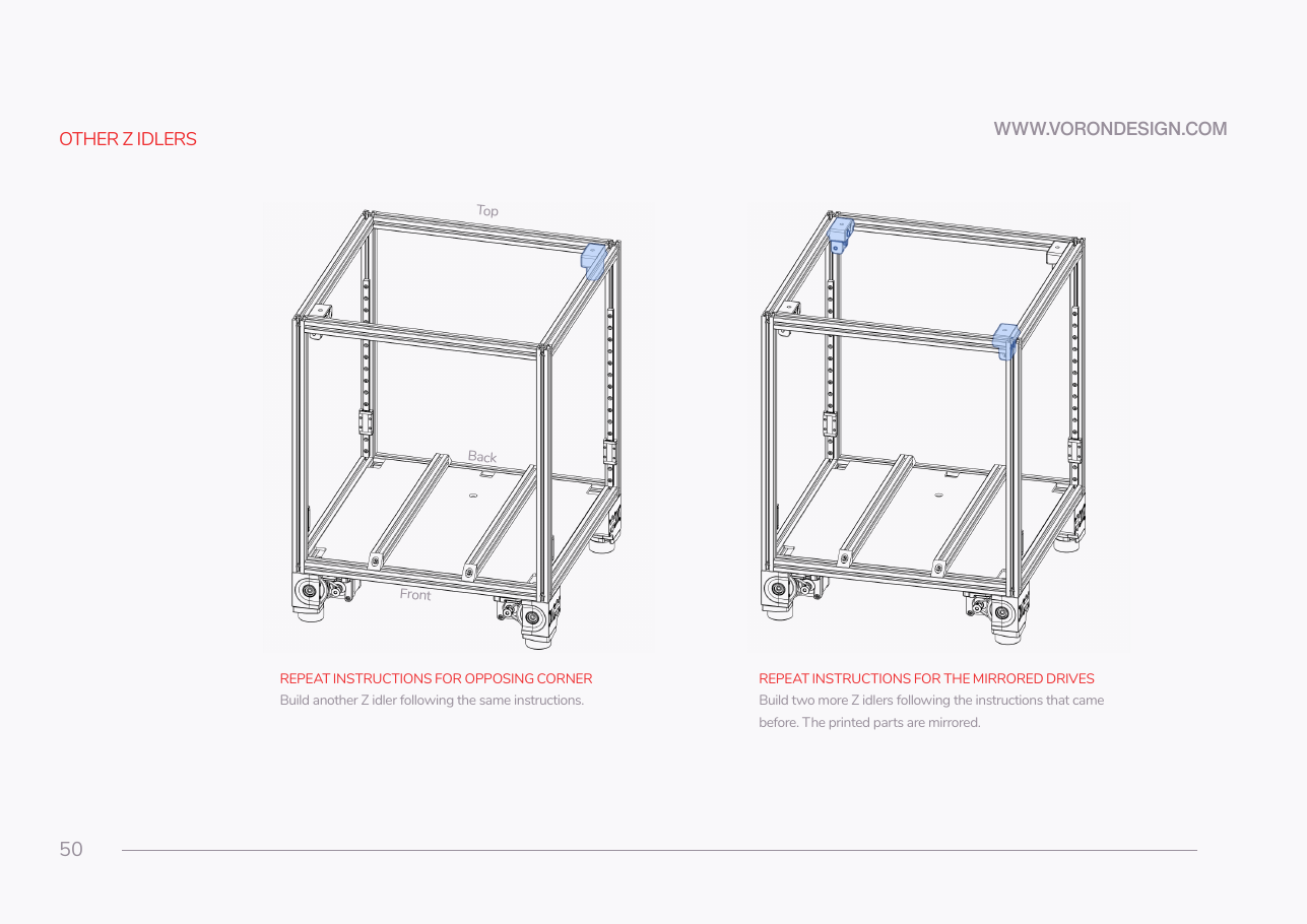 Step 02.43Fit the remaining three Z idlers

Gather per session — what to lay out before each bench segment.
- Steps 02.01–02.04 · ~40 min — Fasteners, Tools & Misc box: M3×5×4 brass heat-set insert ×36 · Printed parts:
z_drive_retainer_a×2 (bin 02-Z0, 02-Z2);z_drive_main_a×2 (bin 02-Z0, 02-Z2);z_drive_retainer_b×2 (bin 02-Z1, 02-Z3);z_drive_main_b×2 (bin 02-Z1, 02-Z3) · Tools and consumables: soldering iron with the LDO brass tip · Set out for later steps: all Chapter 02 printed parts from batches B00, B01 and B02 · Already on the bench: the Gate B retainer with its first insert - Steps 02.05–02.08 · ~25 min — Fasteners, Tools & Misc box: M3×8 SHCS ×9; M3 roll-in T-nut ×9 · Linear Rail Kit box: MGN9H 400 mm rail ×1 · Printed parts:
MGN9_rail_guide_x2jigs ×2 (bin 00-jigs) · Tools and consumables: 3 mm hex key as the gap feeler; masking tape, or the rail's plastic shipping stoppers · Set out for later steps: MGN9H 400 mm rail ×3, labelled Z0–Z3 · Already on the bench: the first Z rail and its nine started screws - Steps 02.09–02.10 · ~35 min — Fasteners, Tools & Misc box: M3×8 SHCS ×27; M3 roll-in T-nut ×27 · Linear Rail Kit box: MGN9H 400 mm rails ×3 · Printed parts:
z_rail_stop_x4×4 (bin 02-Z0, 02-Z1, 02-Z2, 02-Z3) - Steps 02.11–02.16 · ~30 min — Fasteners, Tools & Misc box: M5 roll-in T-nut ×4 · Panel Kit box (carton 2): deck panel ×1 · Printed parts:
deck_support_3mm_x8×8 (bin 02-deck) · Tools and consumables: caliper · Set out for later steps:deck_support_4mm_x8×8, only if the panel measures 4 mm · Already on the bench: the four deck T-nuts - Steps 02.17–02.21 · ~35 min — Motion box: 5×60 mm shaft ×4; GT2 20T 9 mm pulley ×4; 625-2RS bearings ×12; GT2 80T pulley ×4 · Fasteners, Tools & Misc box: M4×4 set screws (pre-threadlocked) ×16; M5 precision spacer 1 mm ×16 · Belts, Chains & Fans box: Gates 2GT closed loop 6 mm × 188 mm ×4 · Tools and consumables: caliper · Already on the bench: the four shafts with their 20T pulleys
- Steps 02.22–02.26 · ~35 min — Fasteners, Tools & Misc box: M3×40 SHCS ×24; M5 hexnut ×4; M3×8 SHCS ×12 · Printed parts:
[a]_z_drive_baseplate_a×2 (bin 02-Z0, 02-Z2);[a]_z_drive_baseplate_b×2 (bin 02-Z1, 02-Z3) · Already on the bench: onez_drive_retainer_awith its inserts (bin 02-Z0, 02-Z2); one belted shaft assembly; onez_drive_main_awith its side inserts (bin 02-Z0, 02-Z2); the other three retainers and mains; the other three belted shaft assemblies - Steps 02.27–02.28 · ~25 min — Motion box: GT2 16T pulley ×4 · Fasteners, Tools & Misc box: M4×4 set screws ×8; M3×8 SHCS ×12 · Motor Kit box: NEMA17 Z motor
LDO-42STH48-2004AC×4 · Printed parts:z_motor_mount_a×2 (bin 02-Z0, 02-Z2);z_motor_mount_b×2 (bin 02-Z1, 02-Z3) · Already on the bench: the four Z motors with their 16T pulleys - Steps 02.29–02.37 · ~30 min — Fasteners, Tools & Misc box: M5 roll-in T-nut ×4; M5×40 SHCS ×2; M5×10 BHCS ×2; M5×16 BHCS ×1 · Belts, Chains & Fans box: Rubber foot 38×19 mm ×1 · Printed parts:
[a]_belt_tensioner_a×1 (bin 02-Z0, 02-Z2) · Already on the bench: one complete_adrive; one_amotor and mount assembly; the completed_adrive; the_amotor and mount assembly - Step 02.38 · ~55 min — Fasteners, Tools & Misc box: M5 roll-in T-nut ×12; M5×40 SHCS ×6; M5×10 BHCS ×6; M5×16 BHCS ×3 · Belts, Chains & Fans box: Rubber foot 38×19 mm ×3 · Printed parts:
[a]_belt_tensioner_a×1 (bin 02-Z0, 02-Z2);[a]_belt_tensioner_b×2 (bin 02-Z1, 02-Z3) · Already on the bench: the other three closed drives; the other three motor and mount assemblies - Steps 02.39–02.40 · ~20 min — Motion box: GT2 20T 9 mm idler ×4 · Fasteners, Tools & Misc box: M3×16 SHCS ×4; M3 hexnut ×4; M5×30 BHCS ×4 · Printed parts:
z_tensioner_bracket_a×2 (bin 02-Z0, 02-Z2);[a]_z_tensioner_9mm×4 (bin 02-Z0, 02-Z1, 02-Z2, 02-Z3);z_tensioner_bracket_b×2 (bin 02-Z1, 02-Z3) · Already on the bench: the four idler cages - Steps 02.41–02.44 · ~25 min — Fasteners, Tools & Misc box: M5 roll-in T-nut ×8; M5×30 BHCS ×8 · Already on the bench: one idler of the drive's hand; the remaining three idlers