Chapter 06 — Z axis (and Chapter 06b — Gantry squaring)
Start the chapter · Resume · Read the whole chapter on one page
Before — end of Ch 05: the gantry, on the bench
After — end of Ch 06: gantry on the Z joints, Z belts run
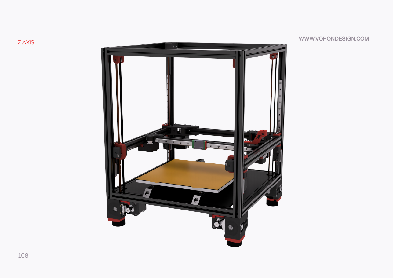 Step 06.1Confirm the starting state
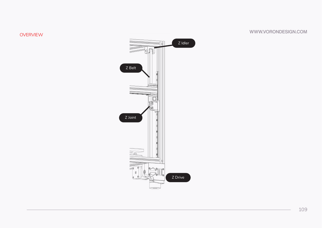
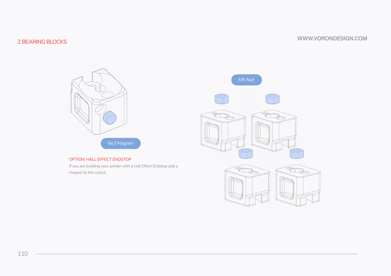 Step 06.3Seat an M5 nut in each Z bearing block
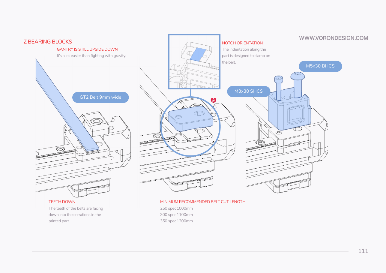 Step 06.5Lay the first belt end under the gantry corner
Step 06.6Fit the lower belt clip
Step 06.7Fit the Z bearing block
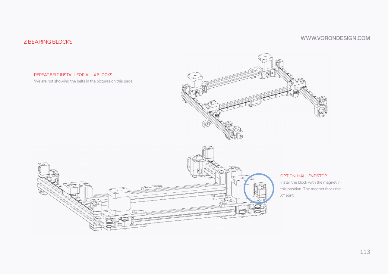 Step 06.8Repeat at all four corners
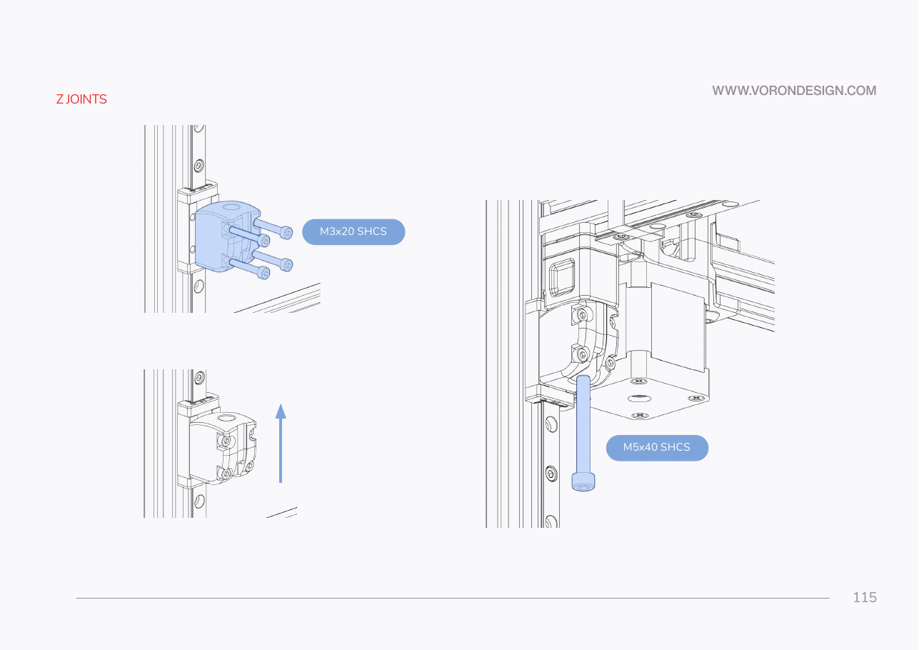 Step 06.9Fit the four lower Z joints to the Z carriages
 Step 06.10Park the four lower joints at a matched heightwith a helper
Step 06.11Turn the gantry over and stage the liftwith a helper
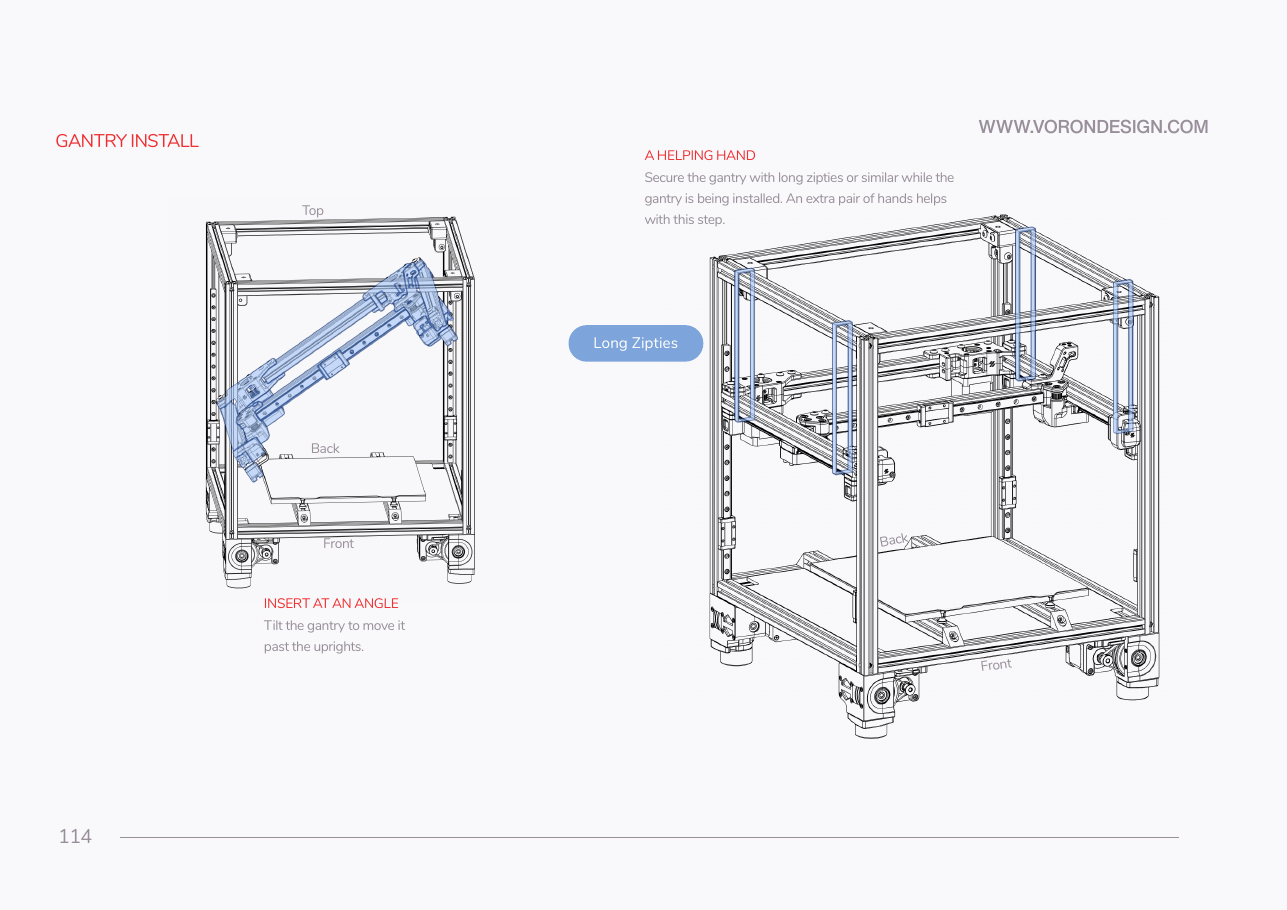 Step 06.12Two-person lift: tilt the gantry into the framewith a helper
Step 06.13Set the gantry down onto the lower jointswith a helper
Step 06.14Bolt the first Z joint together
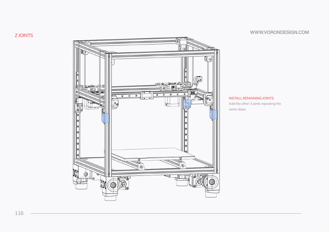 Step 06.15Repeat at the other three joints
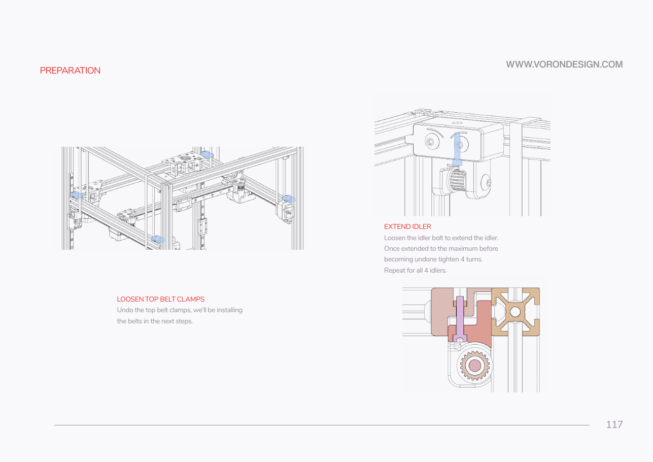 Step 06.16Extend all four Z idlerswith a helper
Step 06.17Loosen the four top belt clamps
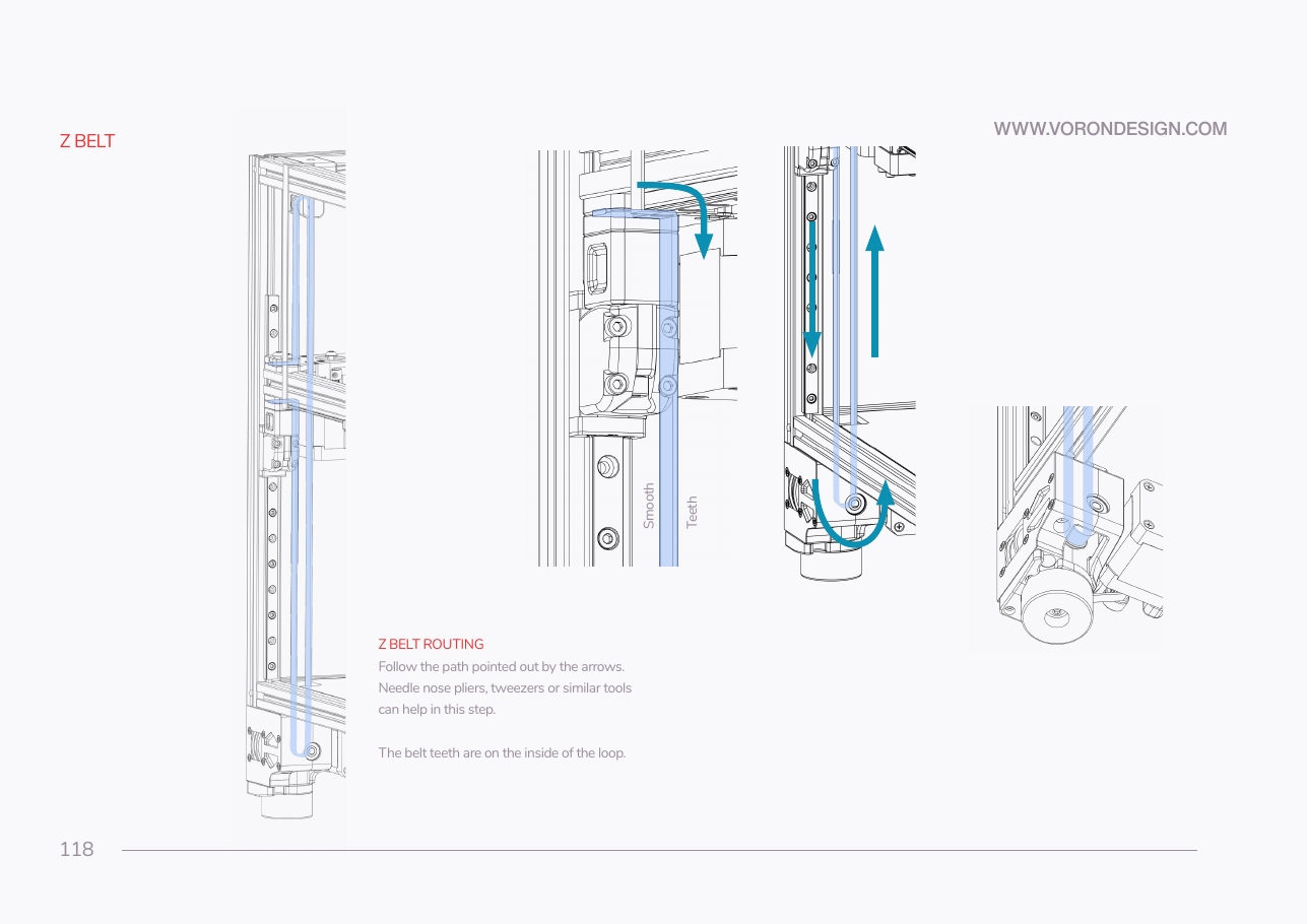 Step 06.18Route the first belt down and around the Z drive
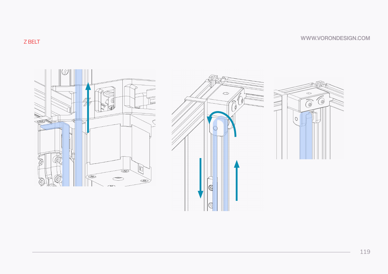 Step 06.19Take the belt up and over the Z idler
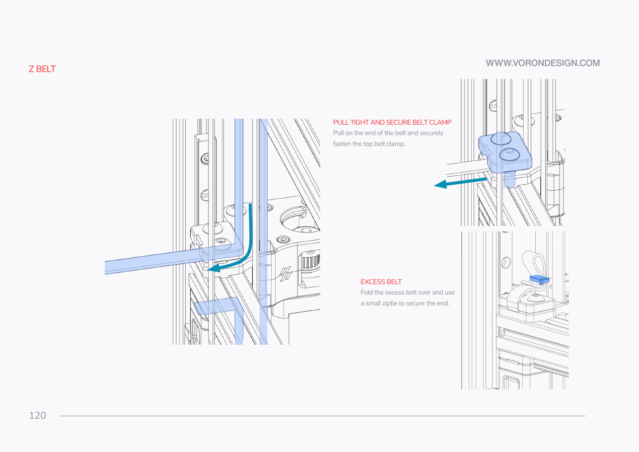 Step 06.20Clamp the second end and pull it tightwith a helper
Step 06.21Trim, fold and tie the excess
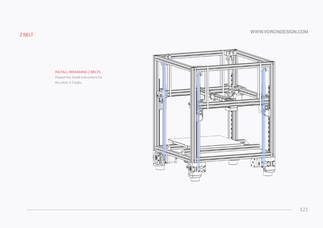 Step 06.22Do the other three Z belts
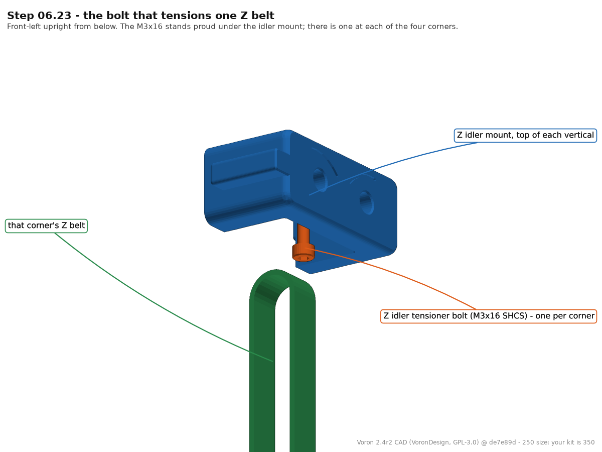 Step 06.23Even the four belts by handwith a helper
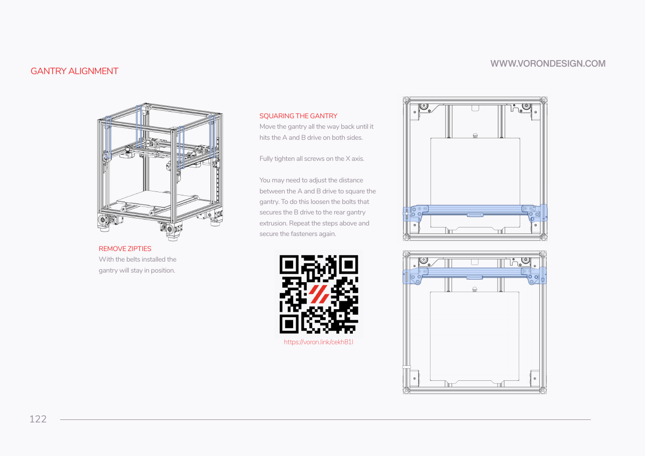 Step 06.24Square the gantry to the A/B drives and lock the X axis
Step 06.25Release the gantry and check it moves freelywith a helper
 Step 06.26Close out the mechanical Z axis
Checkpoint 06Tick before moving on
Step 06b.1Raise the stepper idle timeout
Step 06b.3Set the Z belts to 140 Hzwith a helper
Step 06b.4Park the gantry in the middle
Step 06b.5Disable only the A and B motors
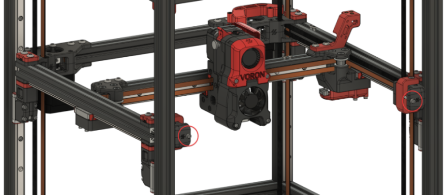 Step 06b.6Release the A/B belt tension completely
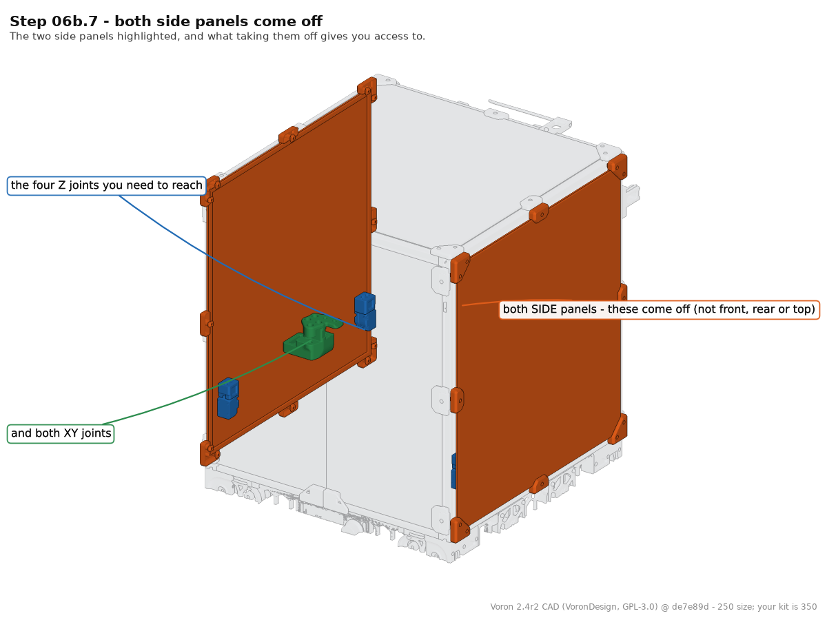 Step 06b.7Confirm access to the Z and XY joints (the side panels are not on yet)
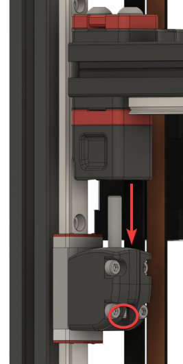 Step 06b.8Unscrew and drop the lower Z jointswith a helper
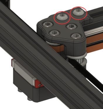 Step 06b.9Partially loosen the X/Y joints
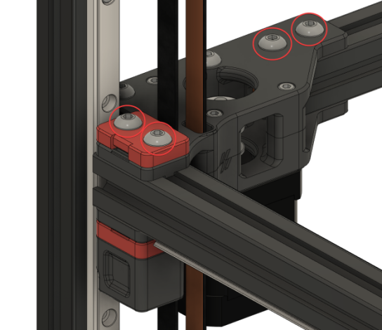 Step 06b.10Partially loosen the A/B joints and the front idlers
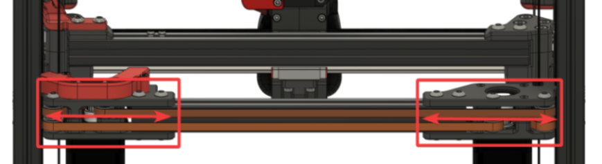 Step 06b.11Level the gantry onto the Z jointswith a helper
Step 06b.12Retighten everything except the X/Y joints
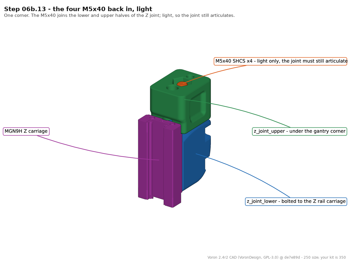 Step 06b.13Reinstall the lower Z joints, lightly
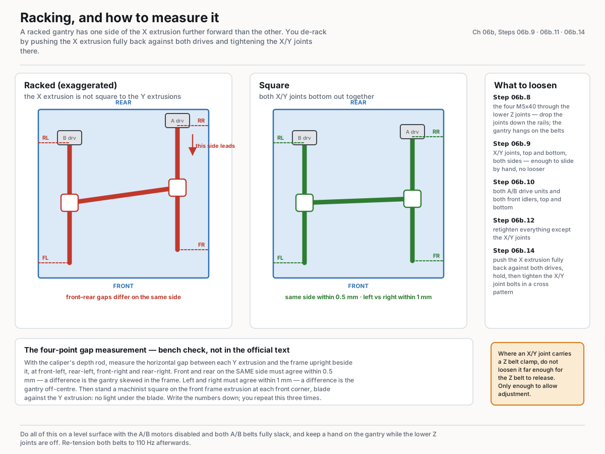 Step 06b.14De-rack the gantry, then tighten the X/Y joints
Step 06b.15Re-tension the A/B belts to 110 Hz (provisional, cold)with a helper
Gather per session — what to lay out before each bench segment.
- Steps 06.1–06.4 · ~30 min — Fasteners, Tools & Misc box: M5 hex nut ×4 · Printed parts:
z_joint_upper_x4×4 (bin 06-Z-joints) · Tools and consumables: Gates 2GT open belt, 9 mm wide, four lengths of about 1400 mm; masking tape - Steps 06.5–06.8 · ~40 min — Fasteners, Tools & Misc box: M3×30 SHCS ×4; M5×30 BHCS ×4 · Printed parts:
[a]_z_belt_clip_lower_x4×4 (bin 06-Z-joints) · Already on the bench: one cut Z belt; one Z bearing block with its M5 nut; the other three cut Z belts; the other three Z bearing blocks - Steps 06.9–06.10 · ~25 min — Fasteners, Tools & Misc box: M3×20 SHCS ×16 · The Z rails: Rubber rail stopper ×4 · Printed parts:
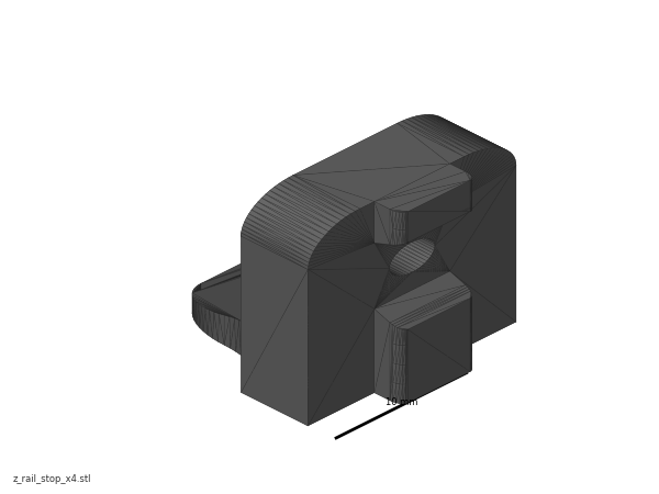
z_joint_lower_x4×4 (bin 06-Z-joints) · Already on the bench: the fourz_rail_stop_x4on the rail tops, if fitted (bin 02-Z0, 02-Z1, 02-Z2, 02-Z3) - Steps 06.11–06.15 · ~45 min — Fasteners, Tools & Misc box: M5×40 SHCS ×4 · Tools and consumables: a towel over the bed; long zip tie, only without the rubber stoppers ×4 · Already on the bench: the gantry
- Steps 06.16–06.21 · ~40 min — Tools and consumables: zip tie, 3×150 mm ×1 · Already on the bench: one Z belt, first end clamped; the same Z belt; the upper belt clip on this corner; the two M5×16 BHCS on top of this corner
- Step 06.22 · ~30 min — Tools and consumables: zip tie, 3×150 mm ×3 · Already on the bench: the other three Z belts
- Steps 06.23–06.25 · ~35 min — nothing to lay out
- Step 06.26 · ~15 min — Set out for later steps:
z_chain_bottom_anchor×1 (bin 10-chains);z_chain_guide×1 (bin 10-chains);[a]_z_chain_retainer_bracket_x2×2 (bin 10-chains); drag chain 10×15 R28 ×1 - Steps 06b.1–06b.16 — Already on the bench: the four Z-joint M5×40 SHCS