Chapter 05 — Gantry: X and Y axes, XY joints, X carriage, titanium backers
Start the chapter · Resume · Read the whole chapter on one page
Before — end of Ch 04: the four bench assemblies
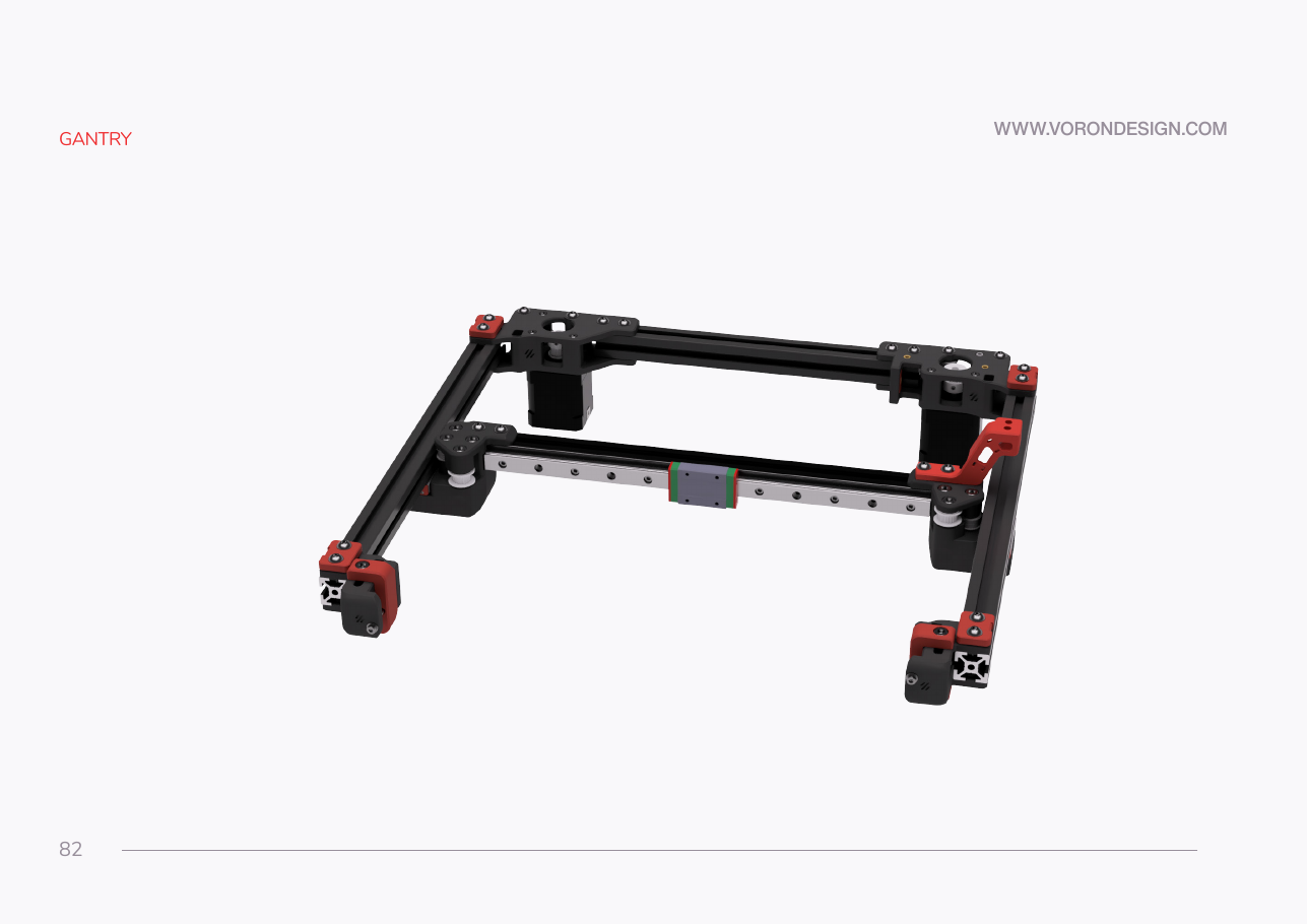
After — end of Ch 05: the gantry, on the bench
 Step 05.1Clear the bench and confirm the sub-assemblies
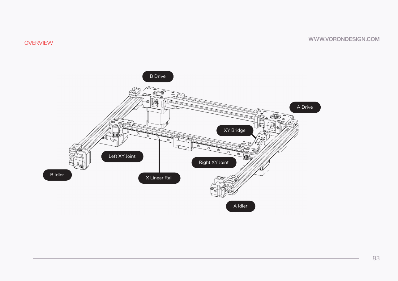 Step 05.2Name the gantry partswith a helper
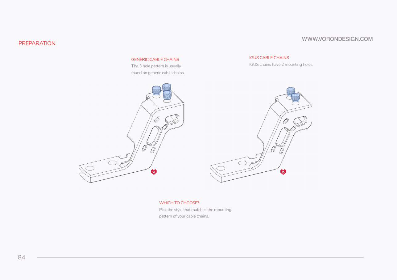 Step 05.3Pick the cable-chain bridge
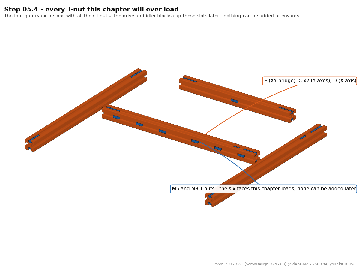 Step 05.4Test-fit T-nuts and stage the fastenerswith a helper
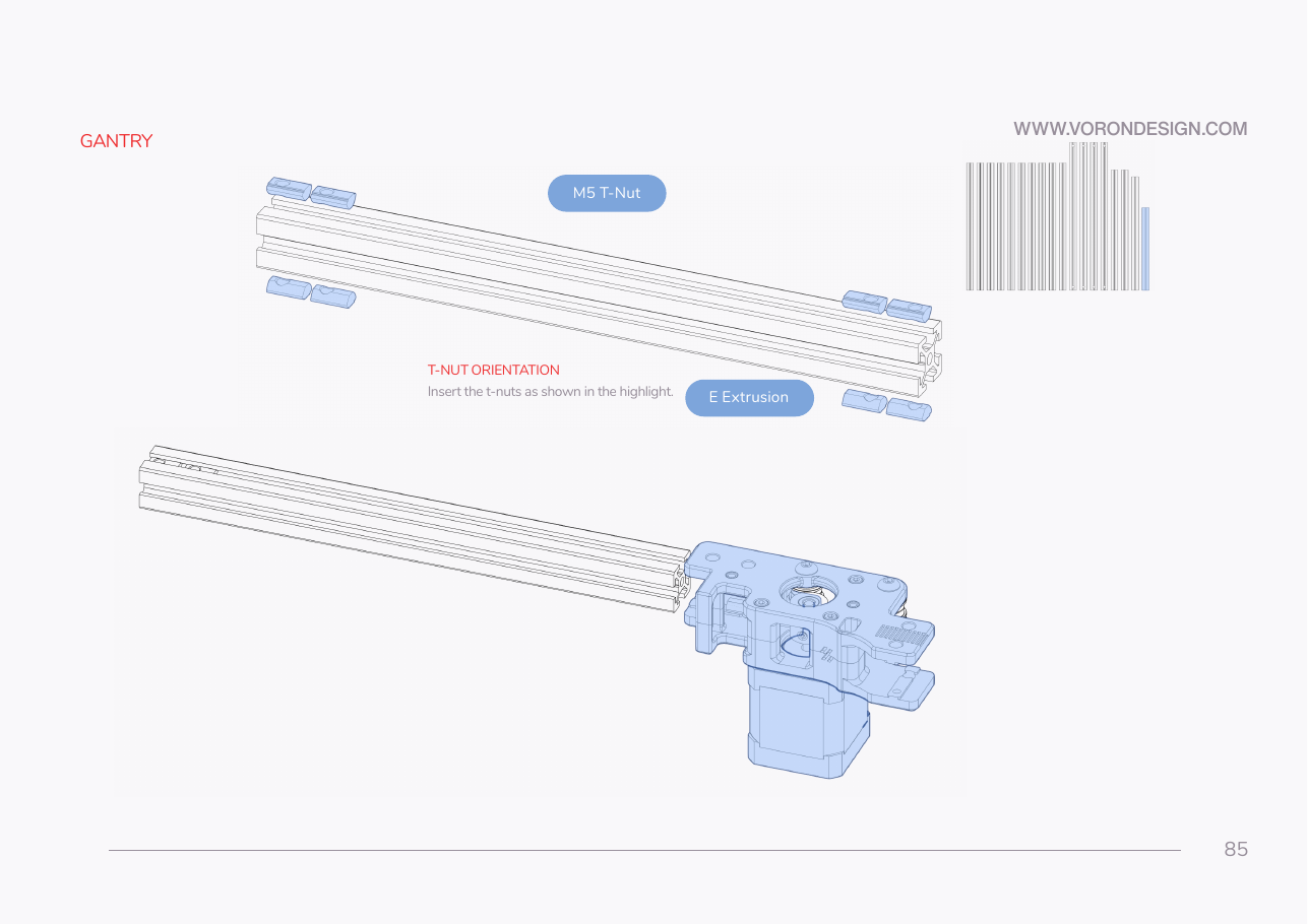 Step 05.5Load the E extrusion (XY bridge)
Step 05.6Slide the A drive onto the E extrusion
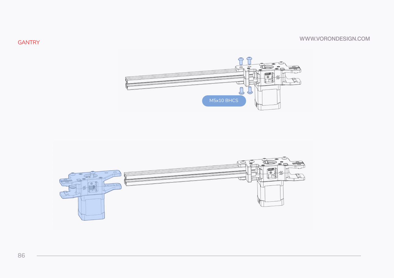 Step 05.7Bolt the A drive to the bridge
Step 05.8Slide the B drive onto the other end
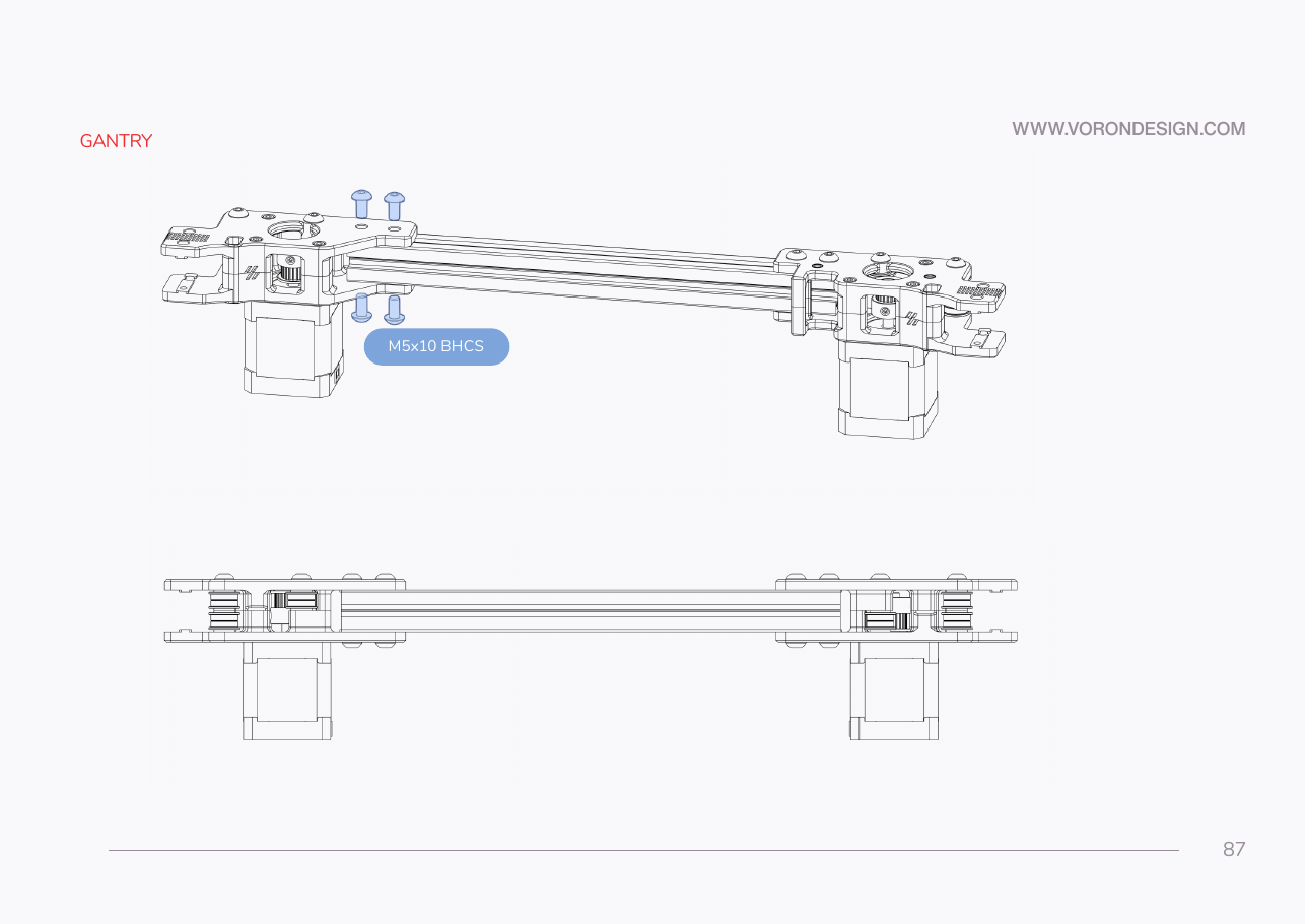 Step 05.9Bolt the B drive and check the bridge
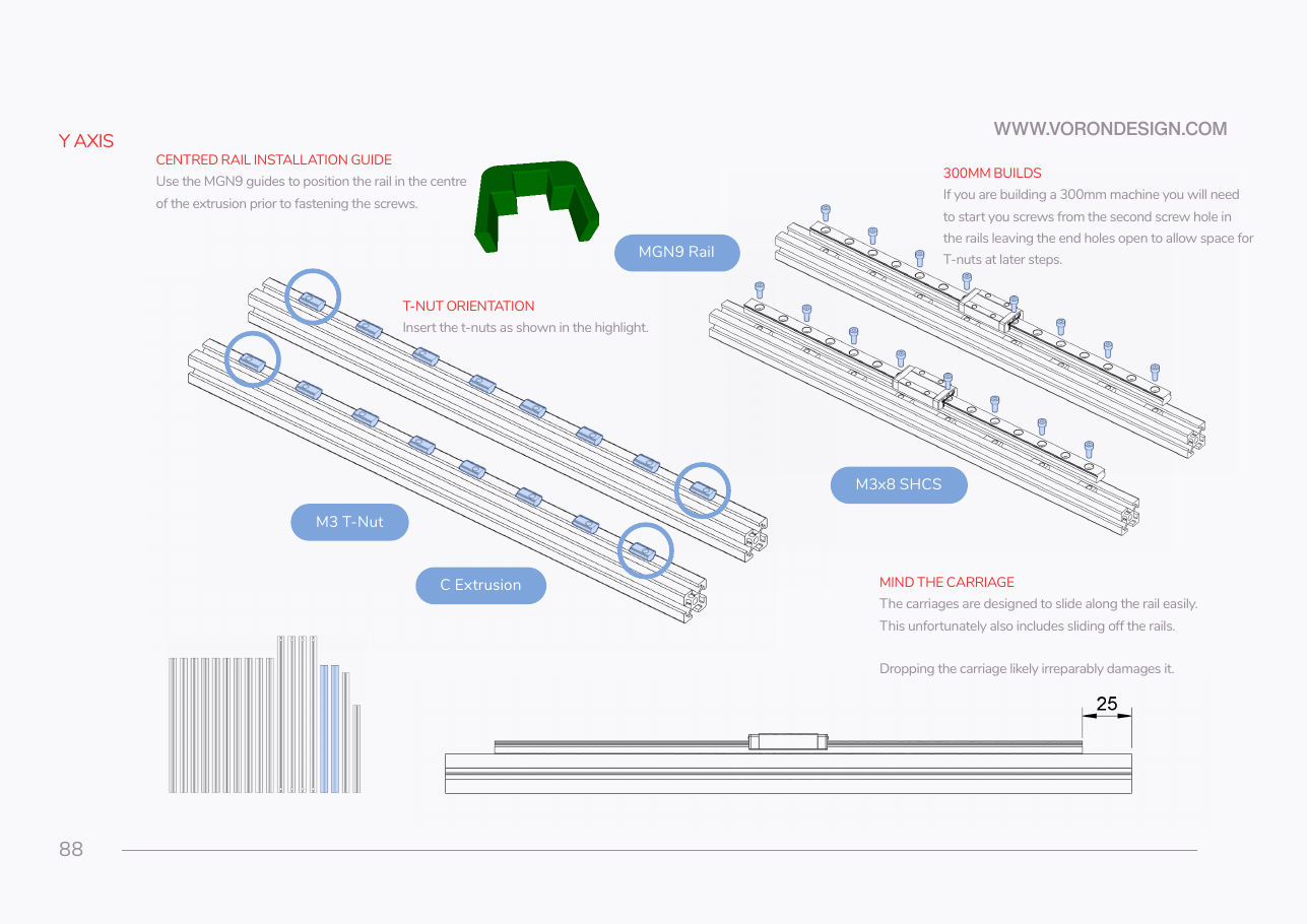 Step 05.10Load M3 T-nuts for the first Y railwith a helper
Step 05.11Centre and start the first MGN9 railwith a helper
Step 05.12Tighten the first Y rail
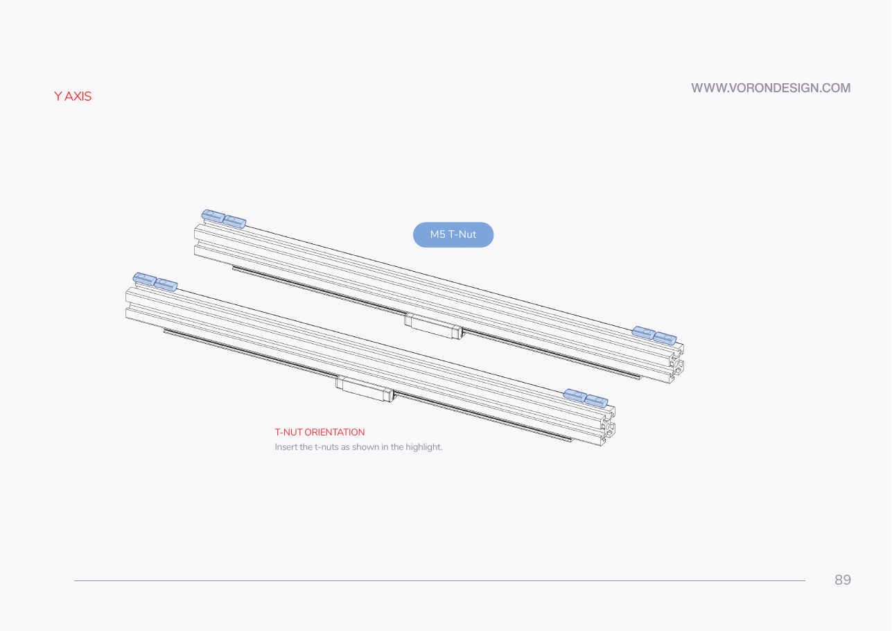 Step 05.13Second Y axis, then load the end M5 T-nuts
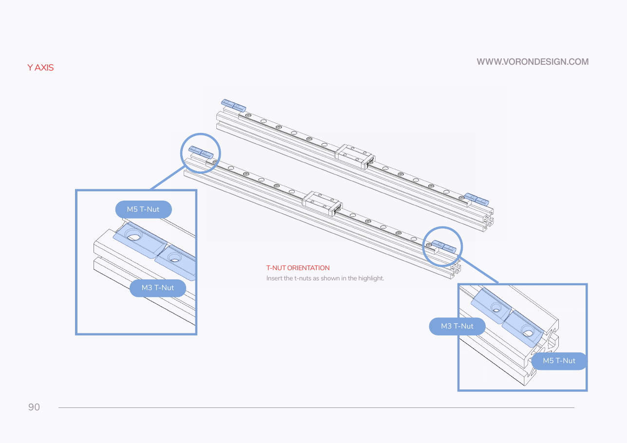 Step 05.14Load the reserved M5 + M3 pair at each endwith a helper
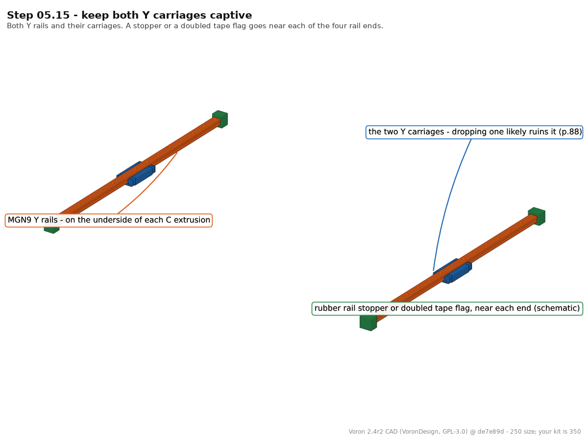 Step 05.15Stop the carriages running off
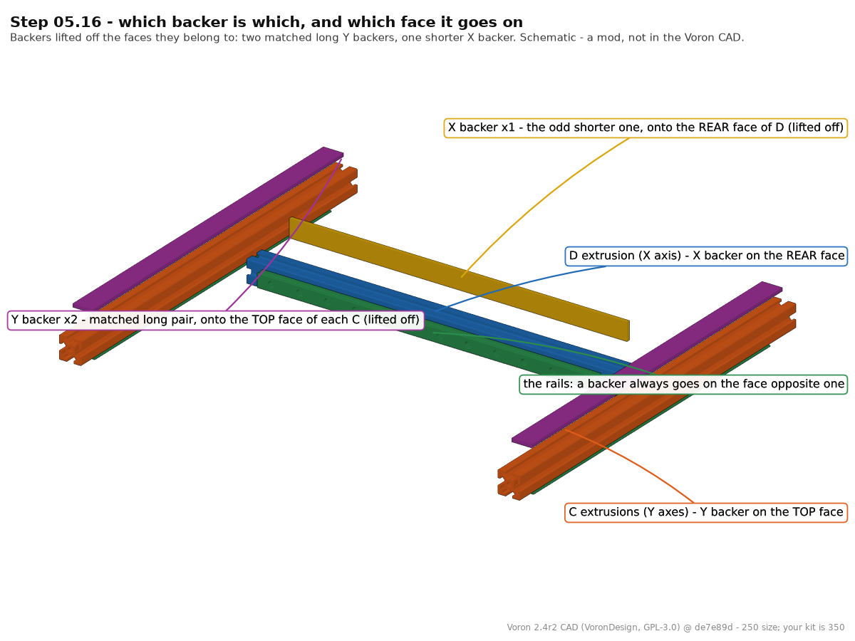 Step 05.16Unpack and identify the titanium backerswith a helper
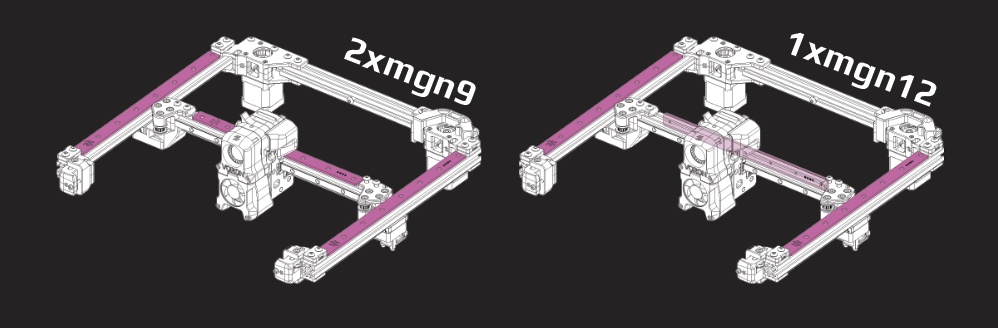 Step 05.17Fit the first Y backerwith a helper
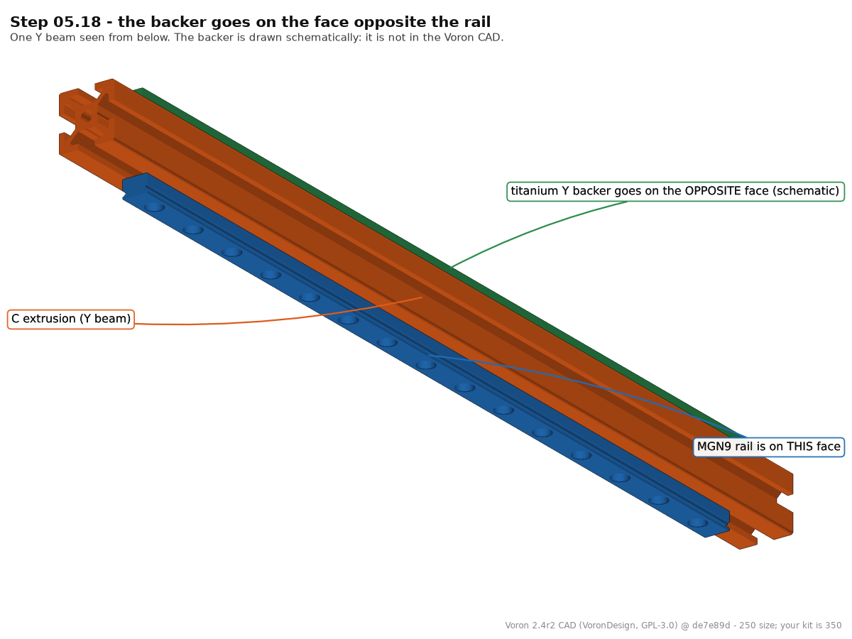 Step 05.18Fit the second Y backer
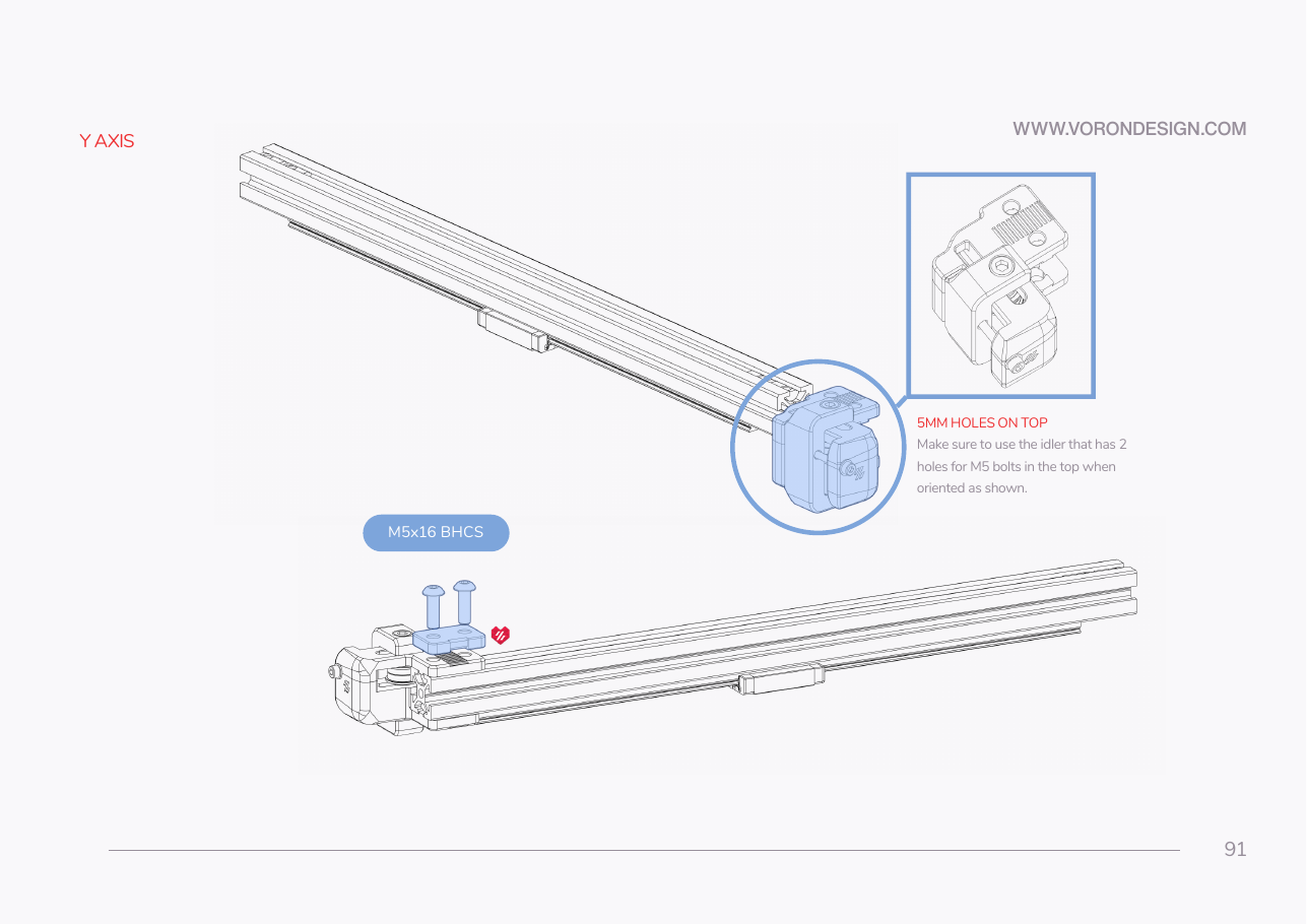 Step 05.19Fit the front idler to the first Y axis
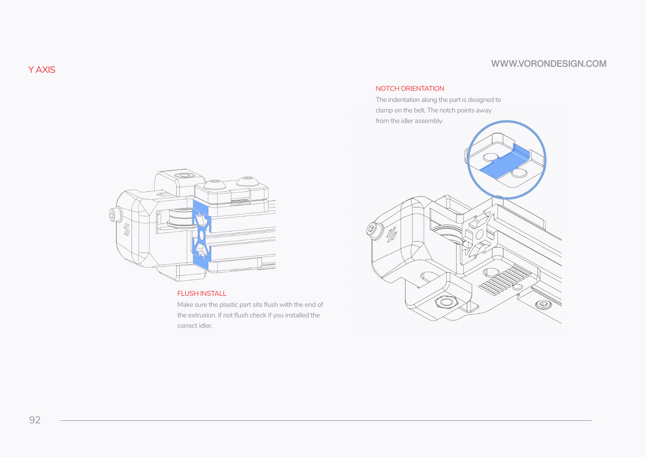 Step 05.20Check flush and notch orientation
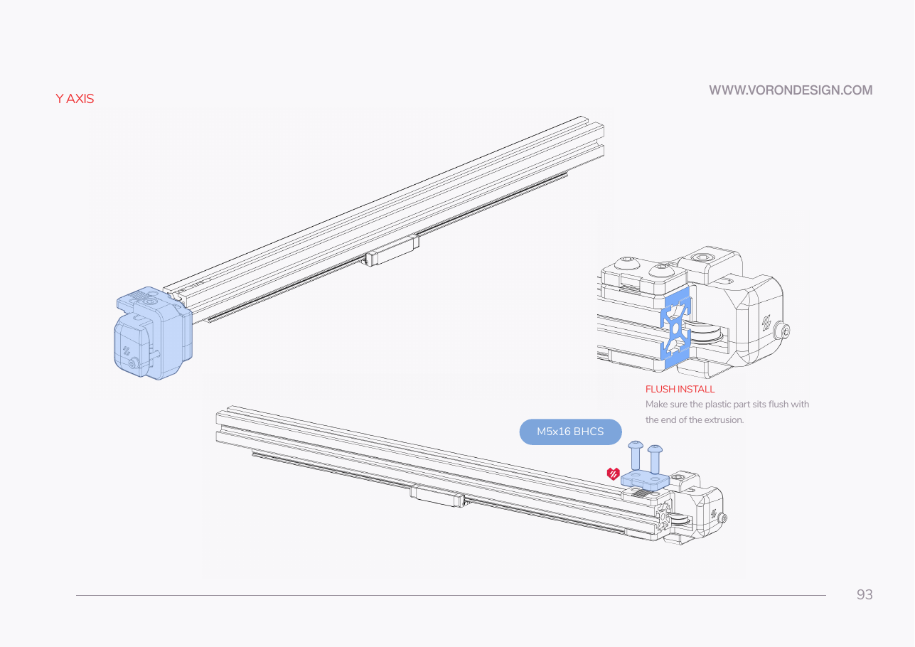 Step 05.21Fit the second front idler
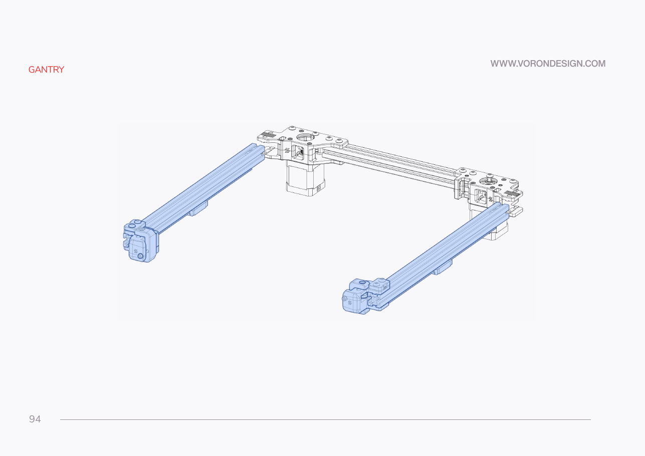 Step 05.22Offer both Y axes to the drive units
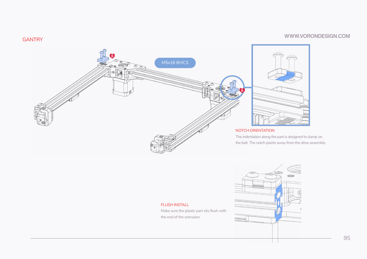 Step 05.23Bolt the Y axes to the drives
Step 05.24Sanity-check the gantry frame, then leave it alonewith a helper
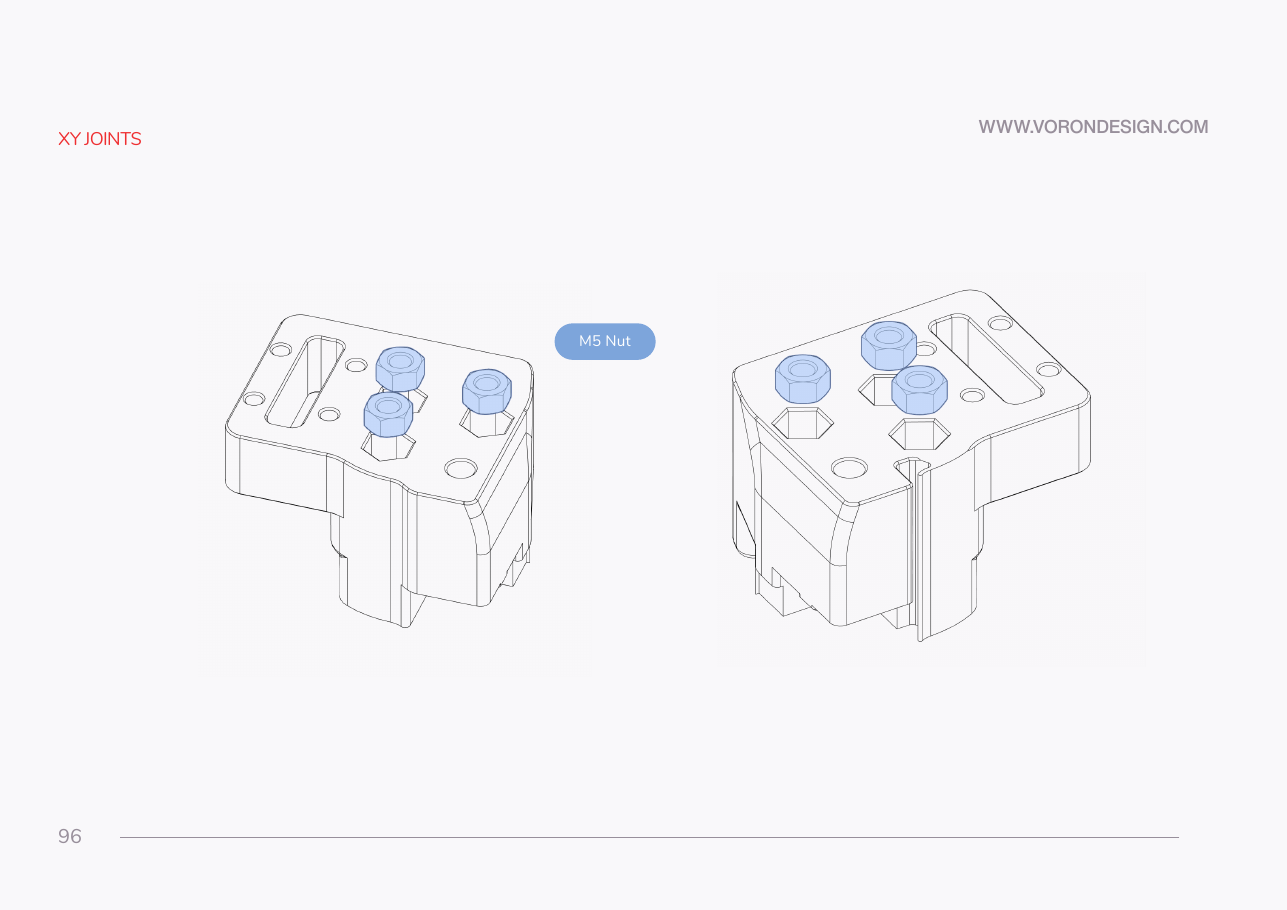 Step 05.25Seat the M5 nuts in both XY joints
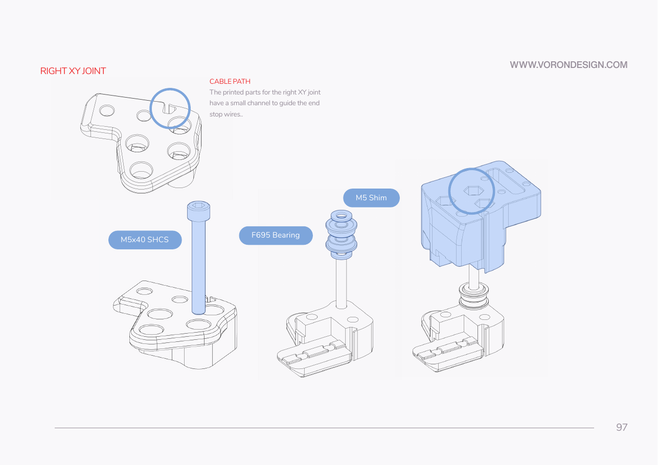 Step 05.26Start the right XY joint bearing stack
Step 05.27Close the right XY joint
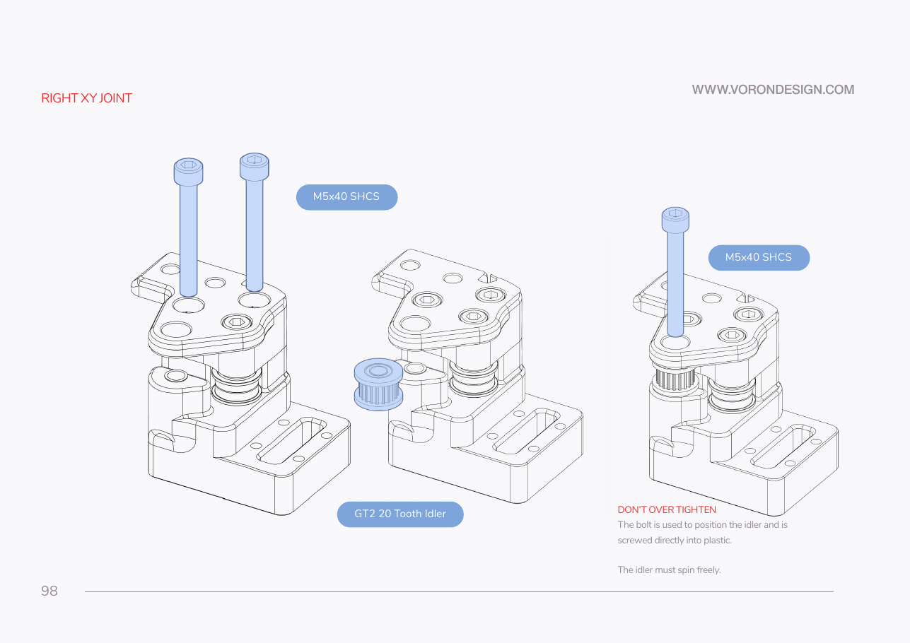 Step 05.28Bolt the right XY joint together
Step 05.29Fit the right joint's 20-tooth idler
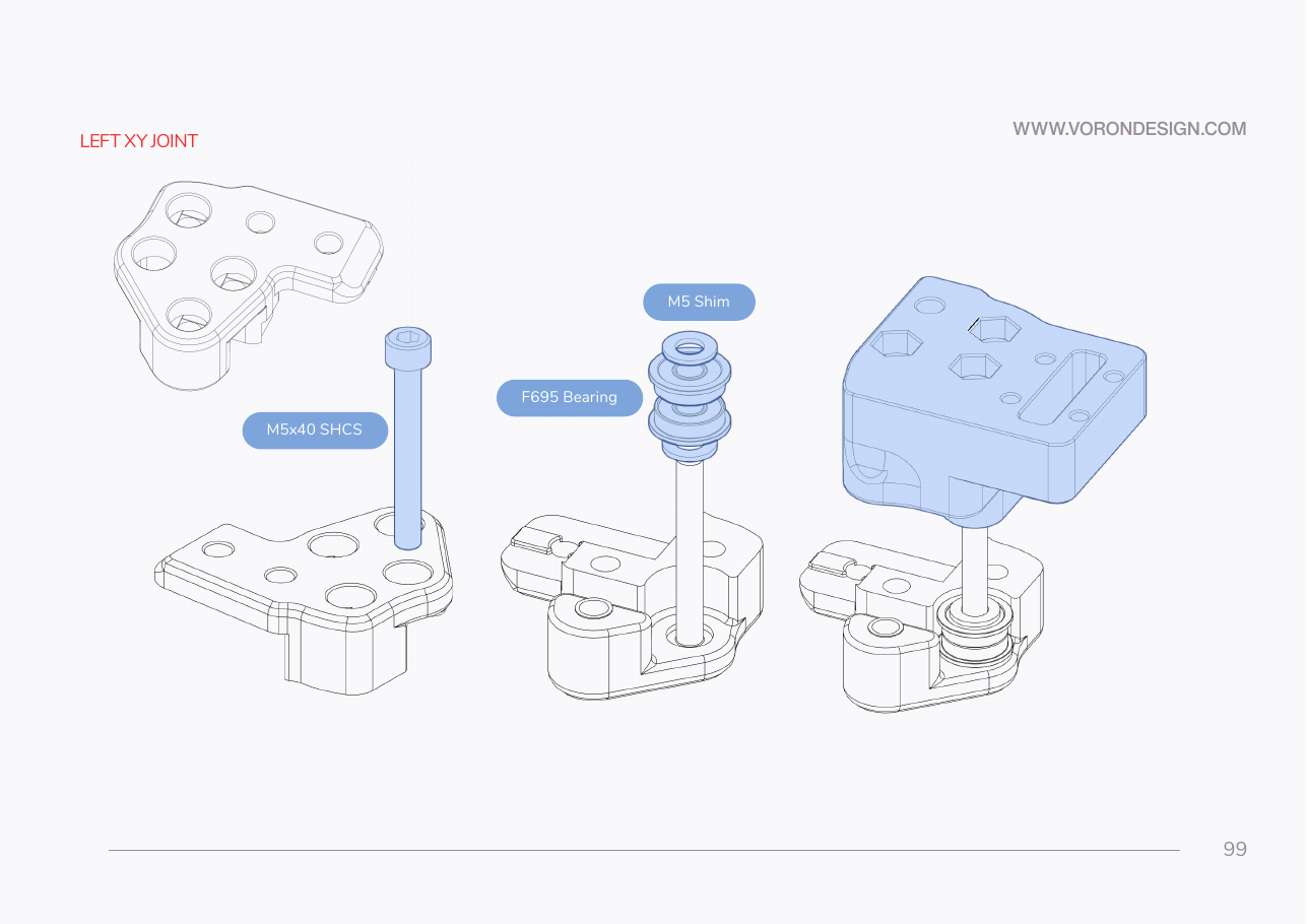 Step 05.30Build the left XY joint
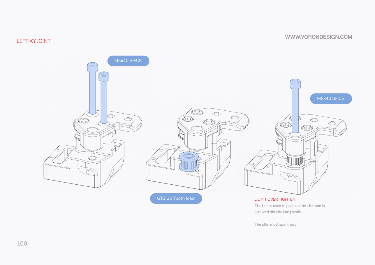 Step 05.31Bolt the left joint and fit its idler
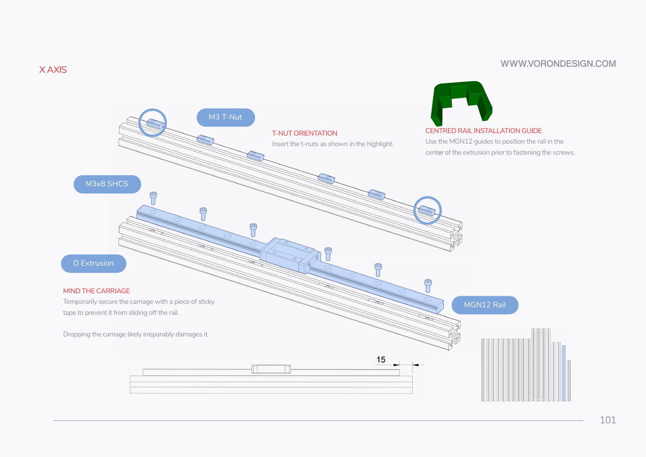 Step 05.32Load M3 T-nuts for the X rail
Step 05.33Centre and fit the MGN12 rail
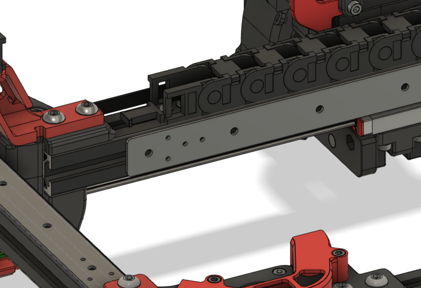 Step 05.34Fit the X backer to the rear face
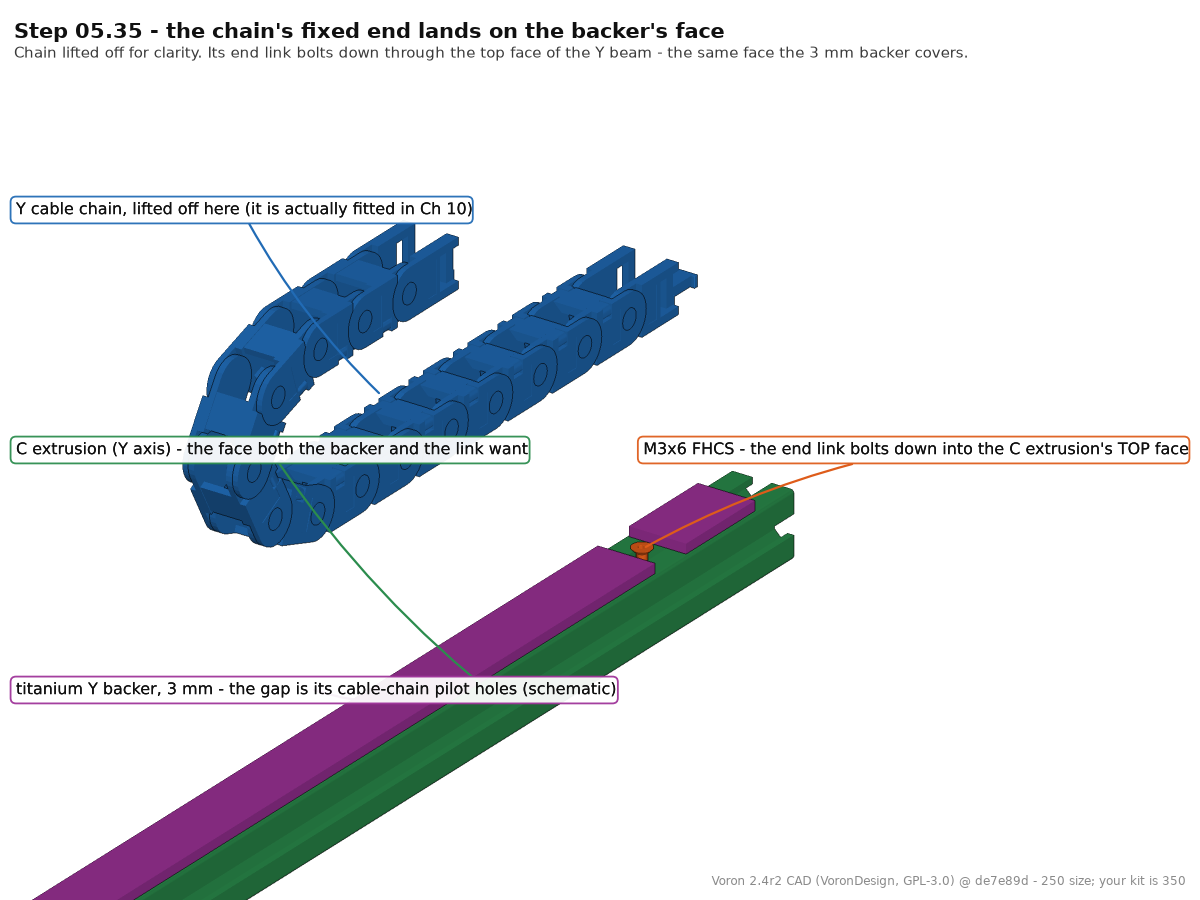 Step 05.35Check backer clearance for the cable chain
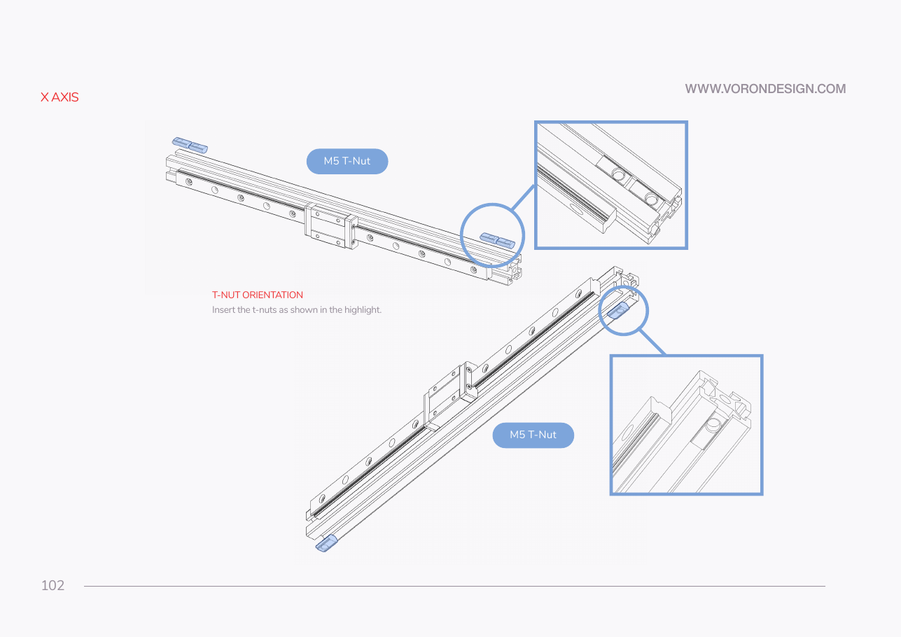 Step 05.36Load the D extrusion's M5 T-nutswith a helper
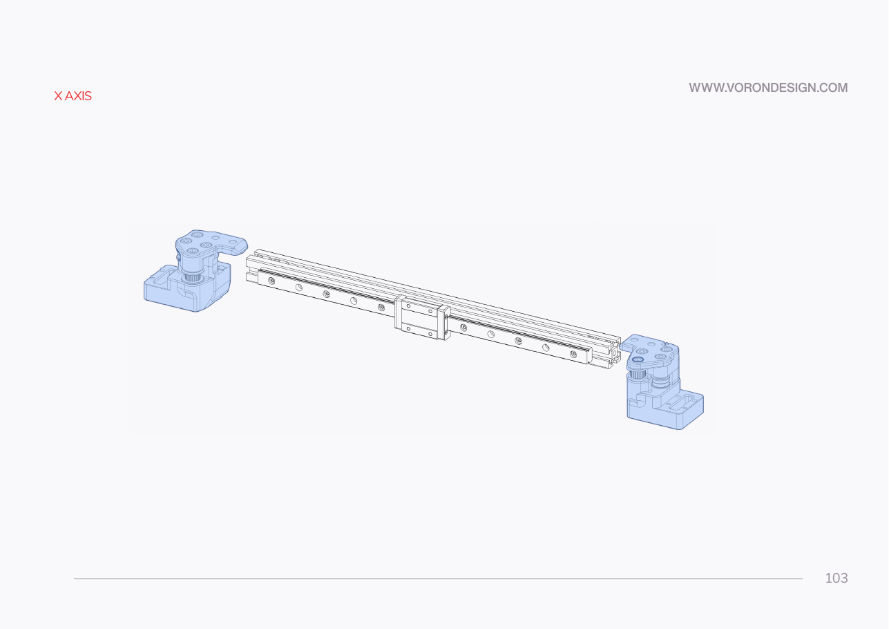 Step 05.37Slide both XY joints onto the X extrusion
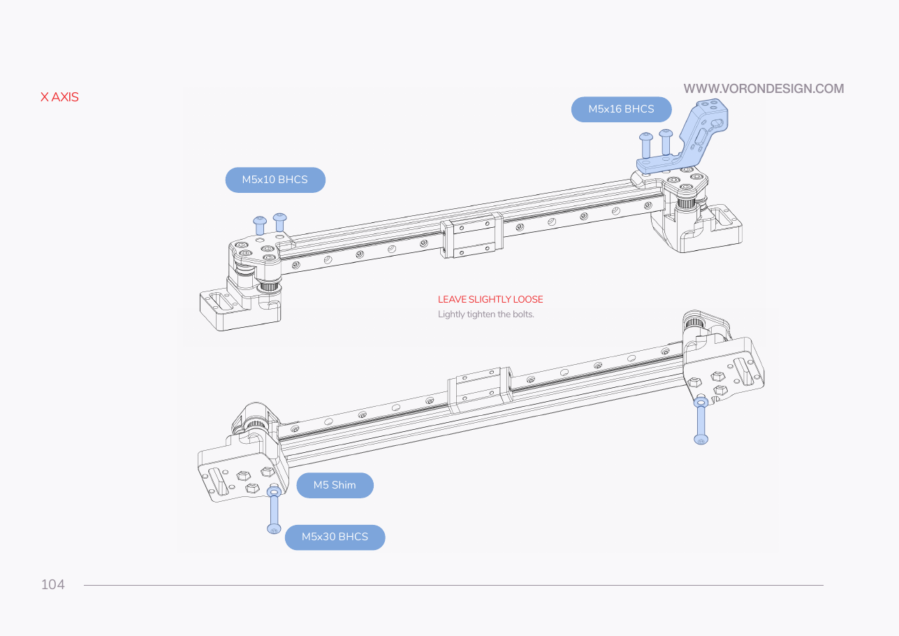 Step 05.38Bolt the joints from above, with the cable bridge
Step 05.39Bolt the joints from below
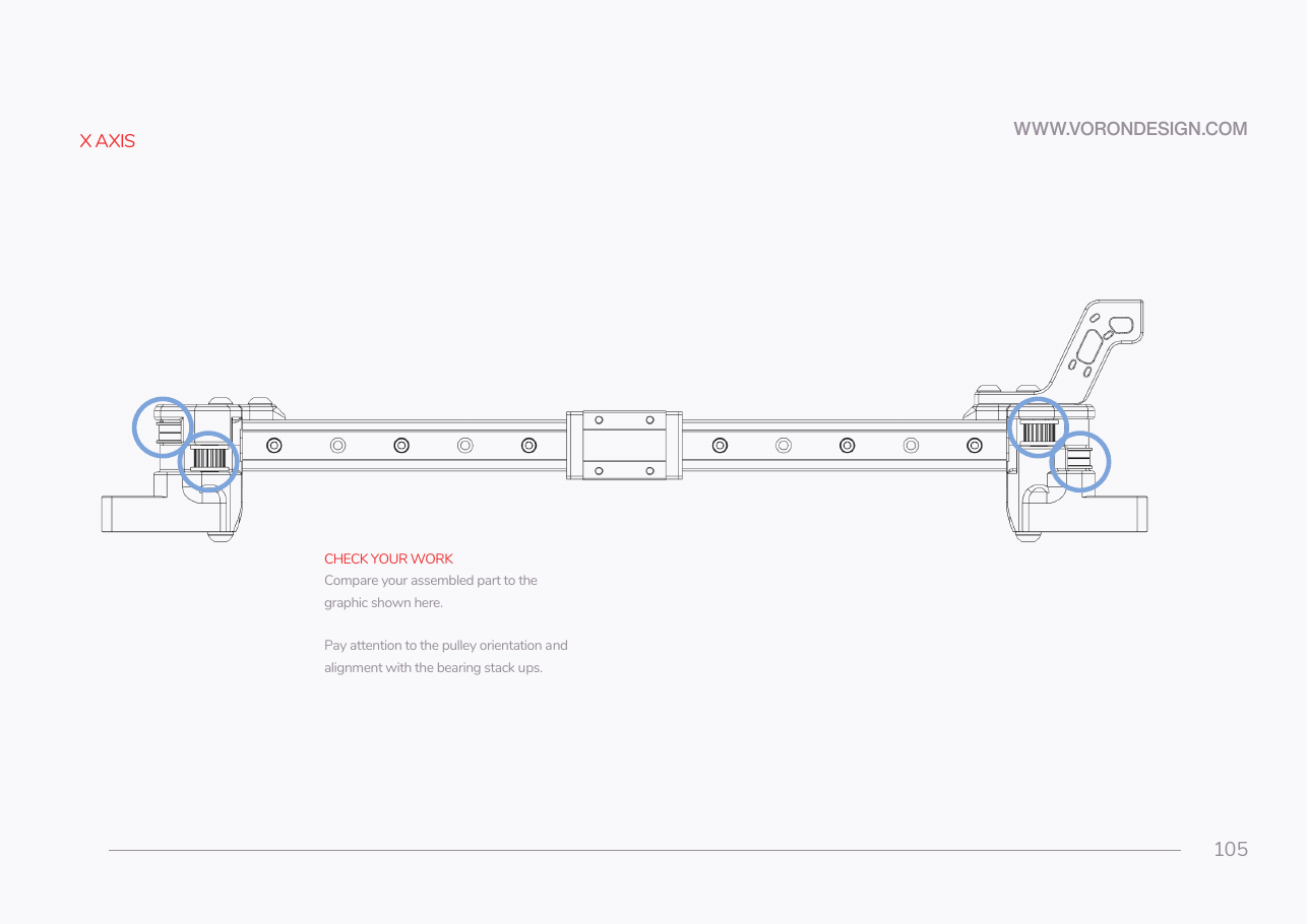 Step 05.40Check the X axis assemblywith a helper
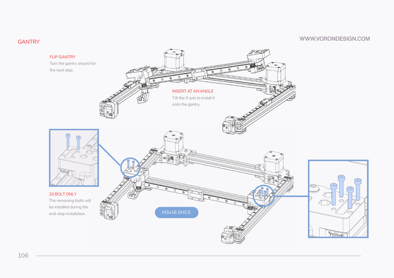 Step 05.41Turn the gantry upside downwith a helper
Step 05.42Insert the X axis at an anglewith a helper
Step 05.43Bolt the XY joints to the Y carriages
Step 05.44Run the X axis end to endwith a helper
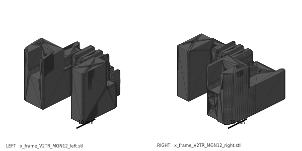 Step 05.45Stage the X-carriage frame halves
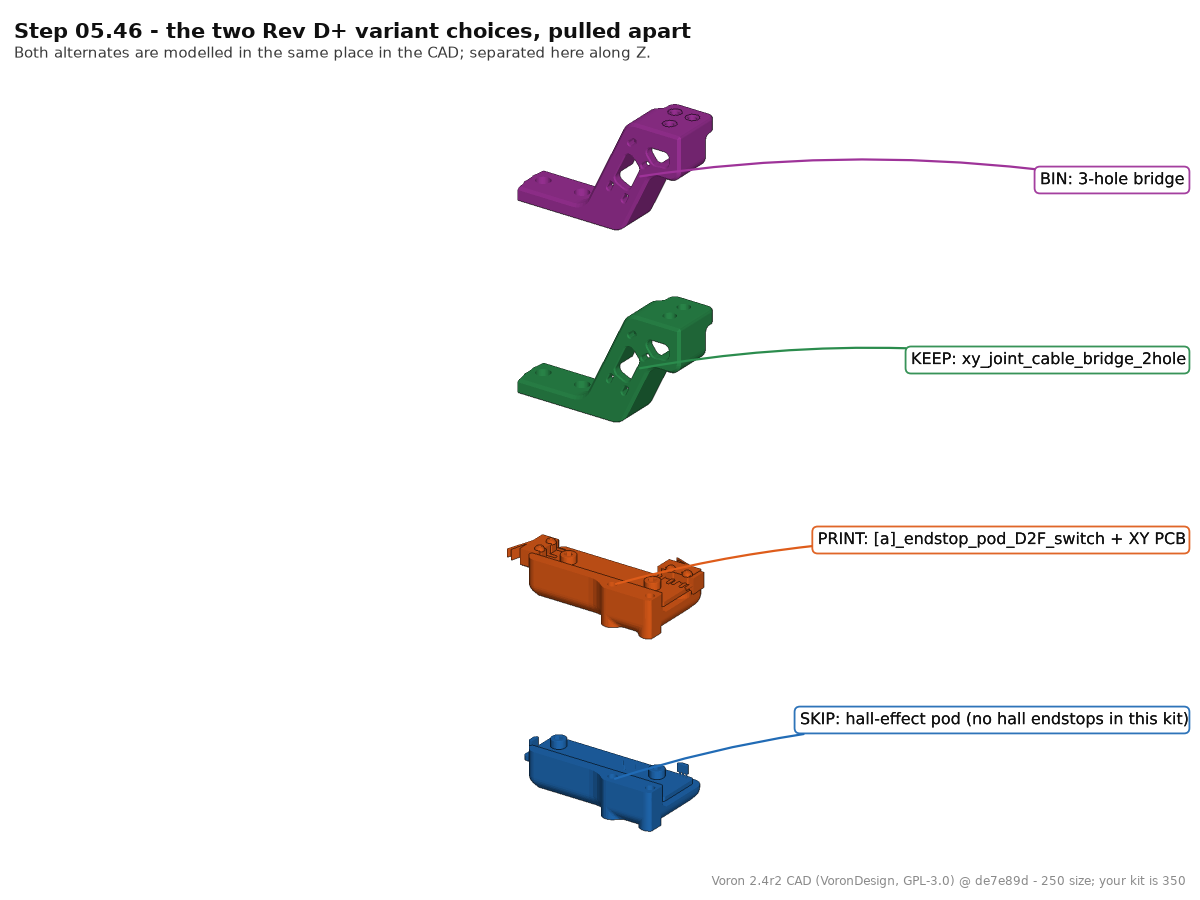 Step 05.46Bag what belongs to later chapterswith a helper
 Step 05.47Stop here: no belts, no squaring
Gather per session — what to lay out before each bench segment.
- Steps 05.1–05.4 · ~25 min — Printed parts:
[a]_xy_joint_cable_bridge_2hole.stl(blue) ×1 (bin 05-XY) · Set out for later steps: C extrusion ×2; D extrusion ×1; E extrusion ×1; M5 roll-in T-nut ×26; M3 roll-in T-nut ×58 · Already on the bench: A drive assembly; B drive assembly; A idler assembly, front right; B idler assembly, front left - Steps 05.5–05.9 · ~30 min — Fasteners, Tools & Misc box: M5 T-nut ×8; M5×10 BHCS ×8 · Frame Kit 2.4-350 box: E extrusion ×1 · Already on the bench: A drive assembly; E extrusion with its eight T-nuts; B drive assembly
- Steps 05.10–05.12 · ~30 min — Fasteners, Tools & Misc box: M3 T-nut ×9; M3×8 SHCS ×9 · Linear Rail Kit box: MGN9H 400 mm rail ×1 · Frame Kit 2.4-350 box: C extrusion ×1 · Tools and consumables:
MGN9_rail_guide_x2jig ×2 (bin 00-jigs) · Already on the bench: M3×8 SHCS ×9 - Steps 05.13–05.15 · ~30 min — Fasteners, Tools & Misc box: M3 T-nut ×13; M3×8 SHCS ×9; M5 T-nut ×12 · Linear Rail Kit box: MGN9H 400 mm rail ×1 · Frame Kit 2.4-350 box: C extrusion ×1 · Tools and consumables:
MGN9_rail_guide_x2jig ×2 (bin 00-jigs); rubber rail stopper ×4; masking tape, if the stoppers run short - Steps 05.16–05.18 · ~35 min — Fasteners, Tools & Misc box: M3 roll-in T-nut ×20 · Ti backer set: titanium Y backer ×2; M3×8 FHCS ×20 · Tools and consumables: T10 Torx driver · Set out for later steps: titanium X backer ×1; M3×6 FHCS ×9
- Steps 05.19–05.24 · ~40 min — Fasteners, Tools & Misc box: M5×16 BHCS ×8 · Printed parts:
[a]_z_belt_clip_upper_x4(blue) ×4 (bin 05-XY) · Already on the bench: A idler assembly; B idler assembly; both Y assemblies; the bridge and drives assembly - Steps 05.25–05.29 · ~25 min — Motion box: F695 bearing ×2; GT2 20-tooth idler ×1 · Fasteners, Tools & Misc box: M5 nut ×6; M5×40 SHCS ×4; M5 precision spacer ×2 · Printed parts:
xy_joint_left_lower_MGN12×1 (bin 05-XY);xy_joint_right_lower_MGN12×1 (bin 05-XY);xy_joint_right_upper_MGN12×1 (bin 05-XY) · Already on the bench:xy_joint_right_lower_MGN12with its three M5 nuts (bin 05-XY) - Steps 05.30–05.31 · ~20 min — Motion box: F695 bearing ×2; GT2 20-tooth idler ×1 · Fasteners, Tools & Misc box: M5×40 SHCS ×4; M5 precision spacer ×2 · Printed parts:
xy_joint_left_upper_MGN12×1 (bin 05-XY) · Already on the bench:xy_joint_left_lower_MGN12with its three M5 nuts (bin 05-XY) - Steps 05.32–05.35 · ~35 min — Fasteners, Tools & Misc box: M3 T-nut ×16; M3×8 SHCS ×7 · Linear Rail Kit box: MGN12H 400 mm rail ×1 · Frame Kit 2.4-350 box: D extrusion ×1 · Ti backer set: titanium X backer ×1; M3×6 FHCS ×9 · Tools and consumables:
MGN12_rail_guide_x2jig ×2 (bin 00-jigs); T10 Torx driver · Set out for later steps: cable-chain end link, for a dry fit - Steps 05.36–05.40 · ~35 min — Fasteners, Tools & Misc box: M5 T-nut ×6; M5×10 BHCS ×2; M5×16 BHCS ×2; M5×30 BHCS ×2; black M5 washer ×2 · Printed parts:
[a]_xy_joint_cable_bridge_2hole×1 (bin 05-XY) · Already on the bench: left XY joint; right XY joint - Steps 05.41–05.44 · ~30 min — Fasteners, Tools & Misc box: M3×16 SHCS ×6 · Already on the bench: the X axis assembly
- Steps 05.45–05.48 · ~25 min — Tools and consumables: pen · Set out for later steps:
x_frame_V2TR_MGN12_left×1 (bin 07-X);x_frame_V2TR_MGN12_right×1 (bin 07-X);probe_retainer_bracket×1 (bin 07-X); M3×30 SHCS ×2;[a]_endstop_pod_D2F_switch×1 (bin 05-XY);[a]_cable_cover×1 (bin 07-X)