Chapter 11 — Skirts, panels, Clicky-Clack door, filtration
Start the chapter · Resume · Read the whole chapter on one page
Before — end of Ch 09: the bay populated
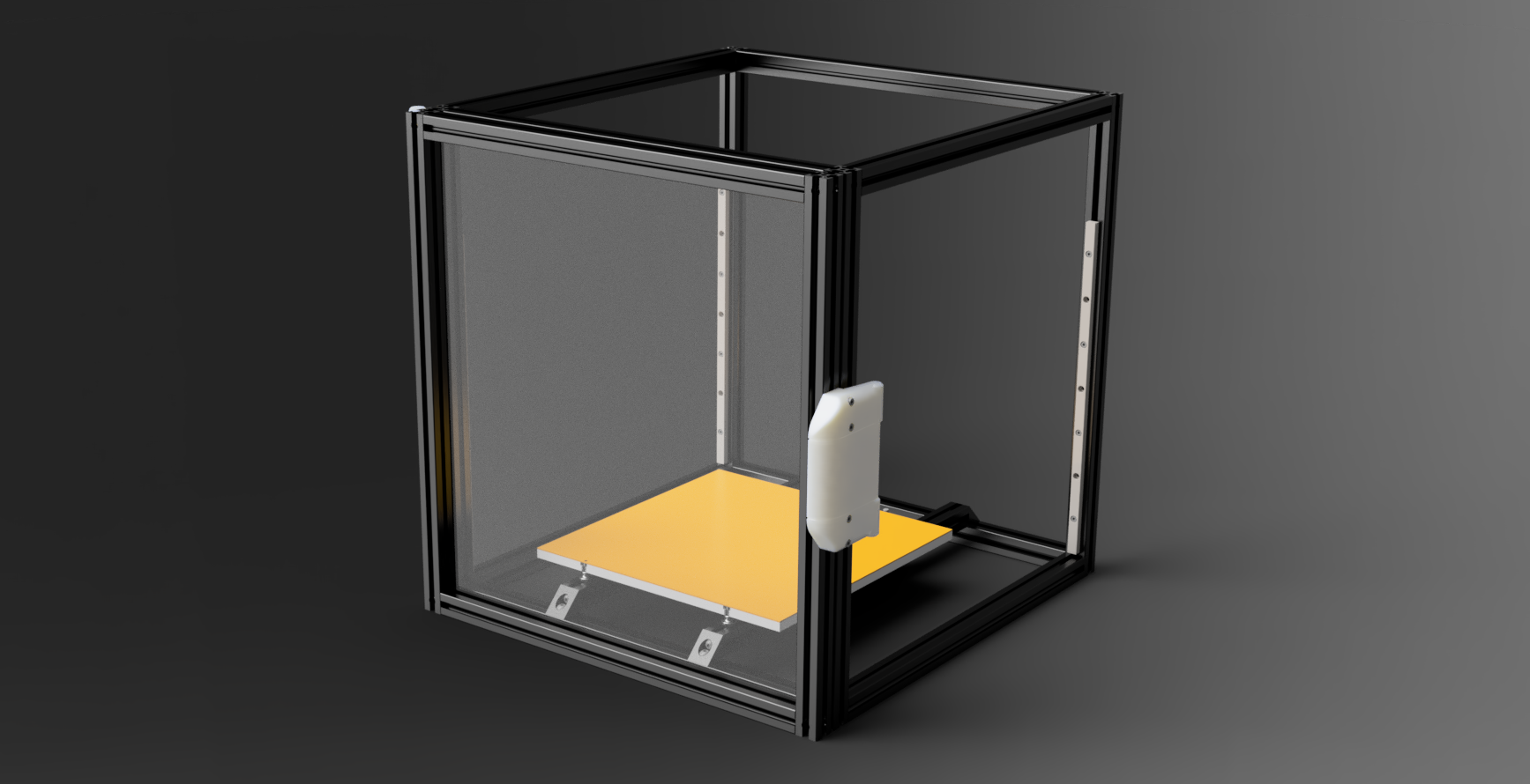
After — end of Ch 11: the machine closed up
Step 11.67Shut down, unplug and prove it dead
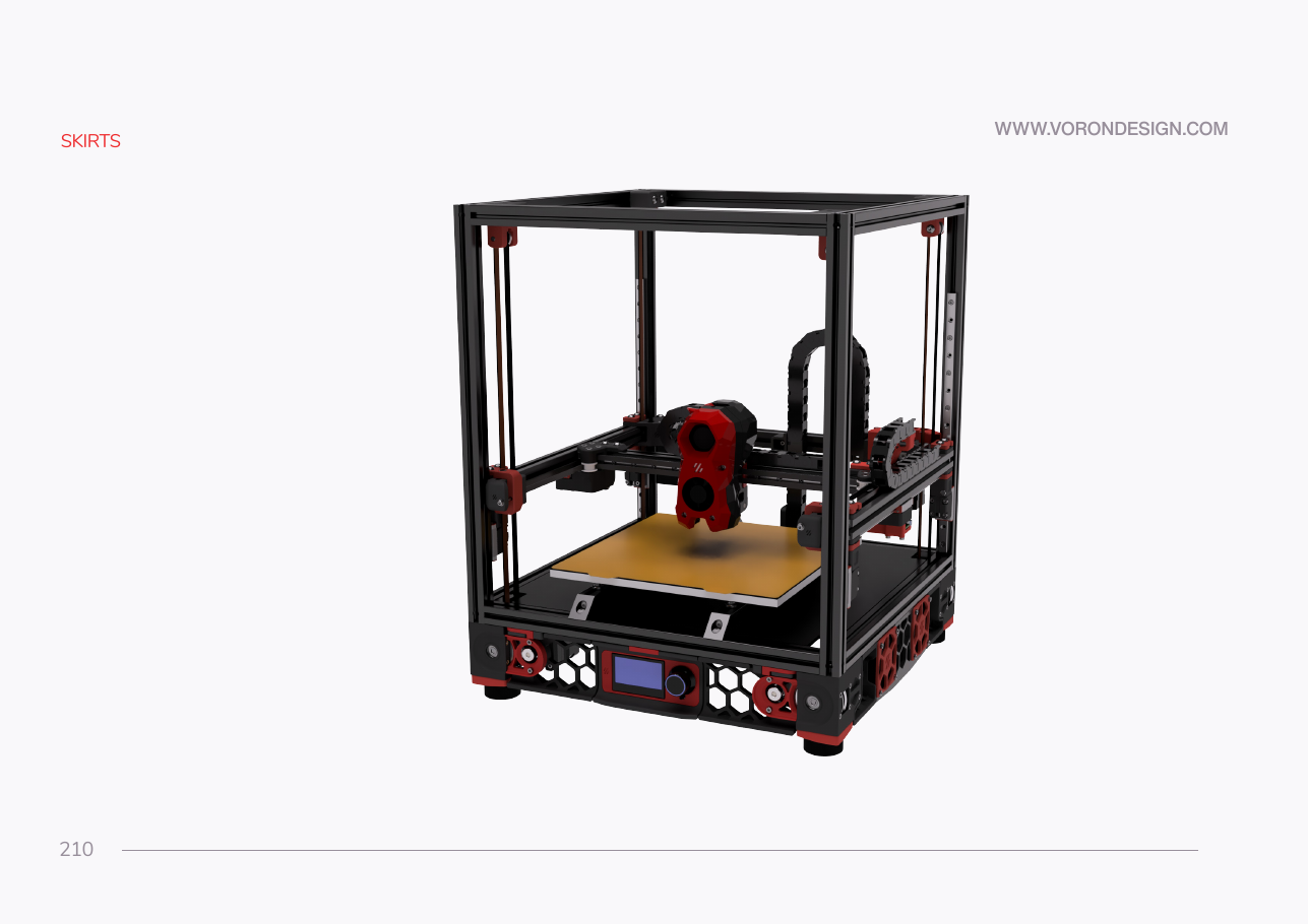 Step 11.1Dry-fit the whole skirt ringwith a helper
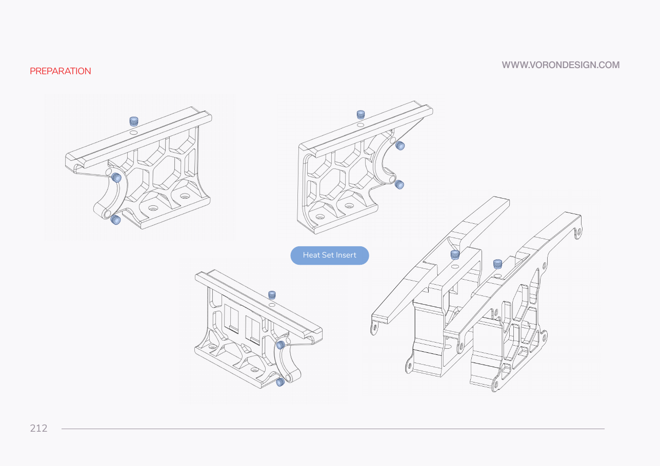 Step 11.2Heat-set the skirt segments
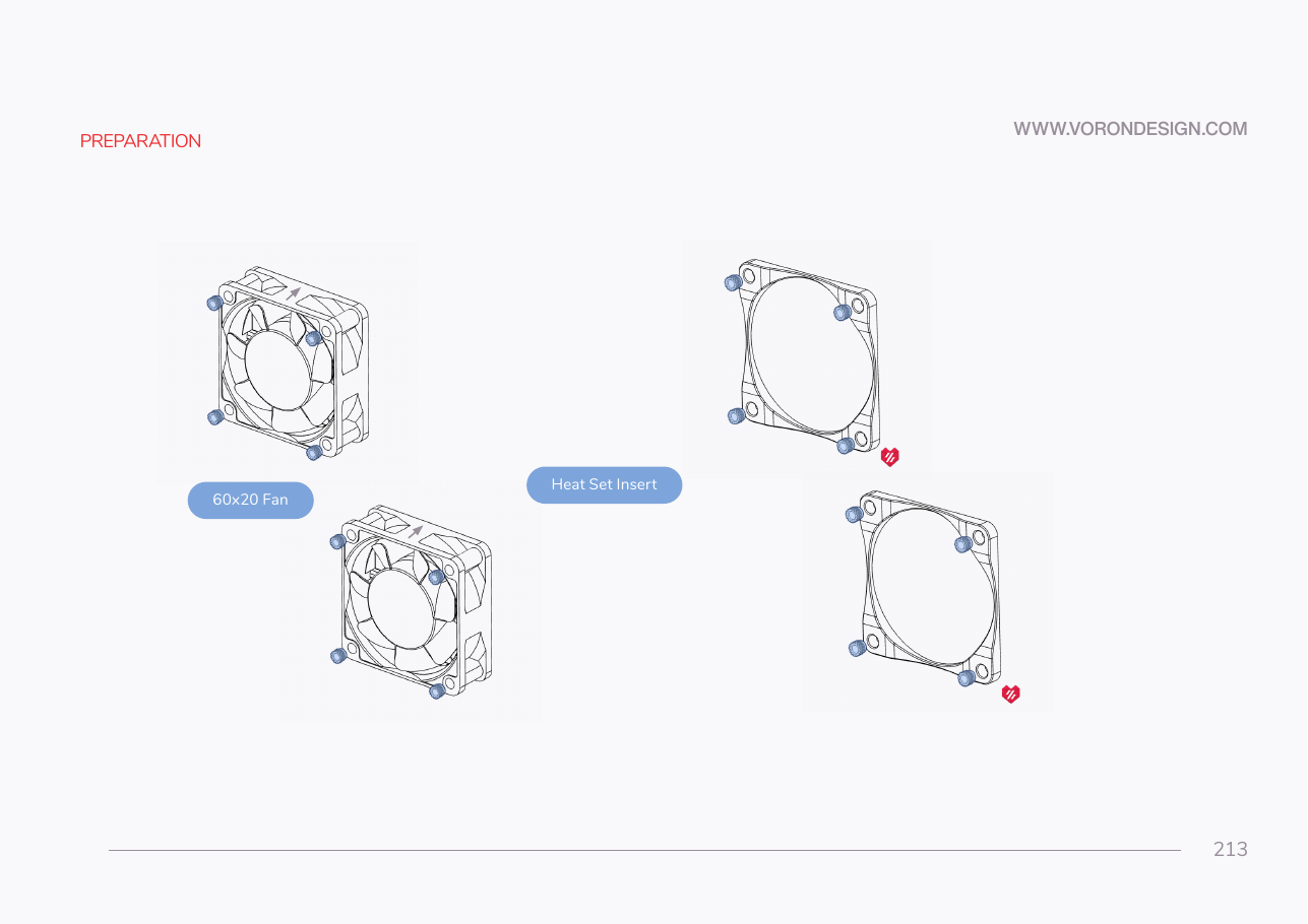 Step 11.3Heat-set the bay fans and the fan grill retainers
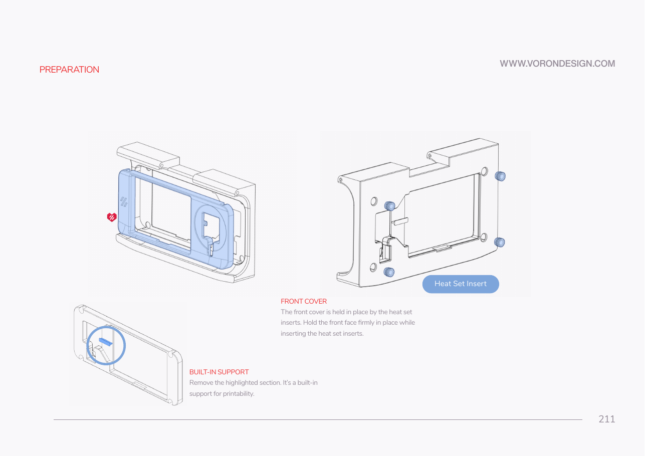 Step 11.4Do not build the mini12864 modulewith a helper
Step 11.5Heat-set and face the BTT TFT4.3 mount
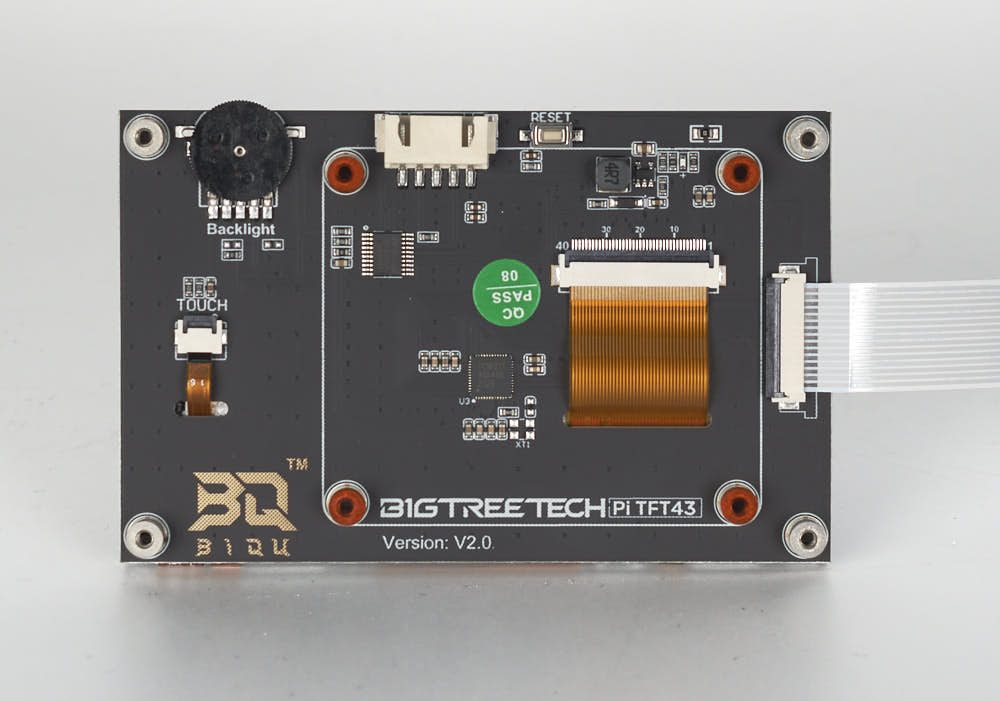 Step 11.6Fit the BTT Pi TFT4.3 screen into the mountwith a helper
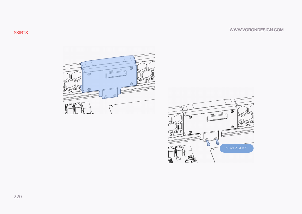 Step 11.7Fit the touchscreen module into the front skirt runwith a helper
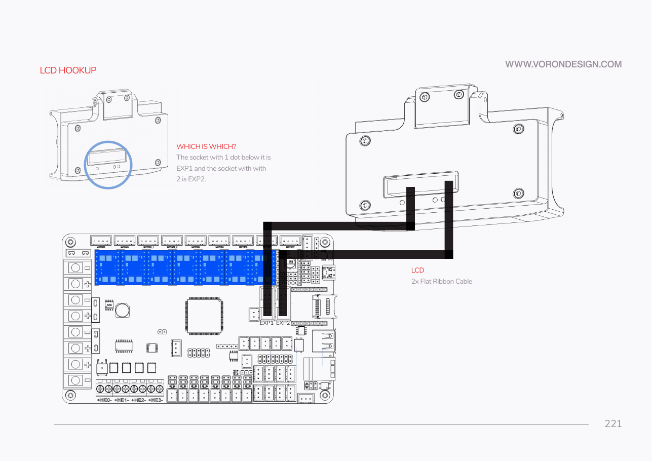 Step 11.8Route and connect the FFC ribbon to the Pi
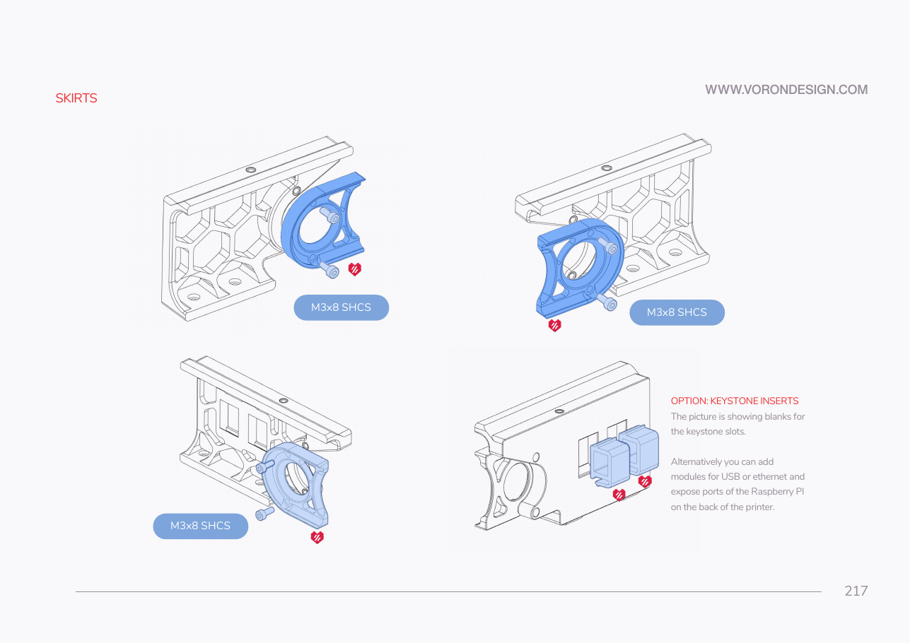 Step 11.9Fit the belt guards to the skirt segmentswith a helper
Step 11.10Populate the keystone panel
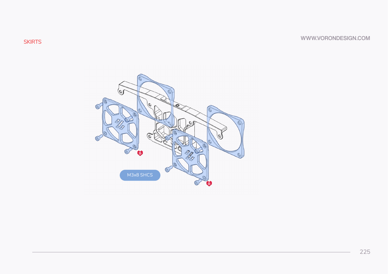 Step 11.11Build the electronics-bay fan moduleswith a helper
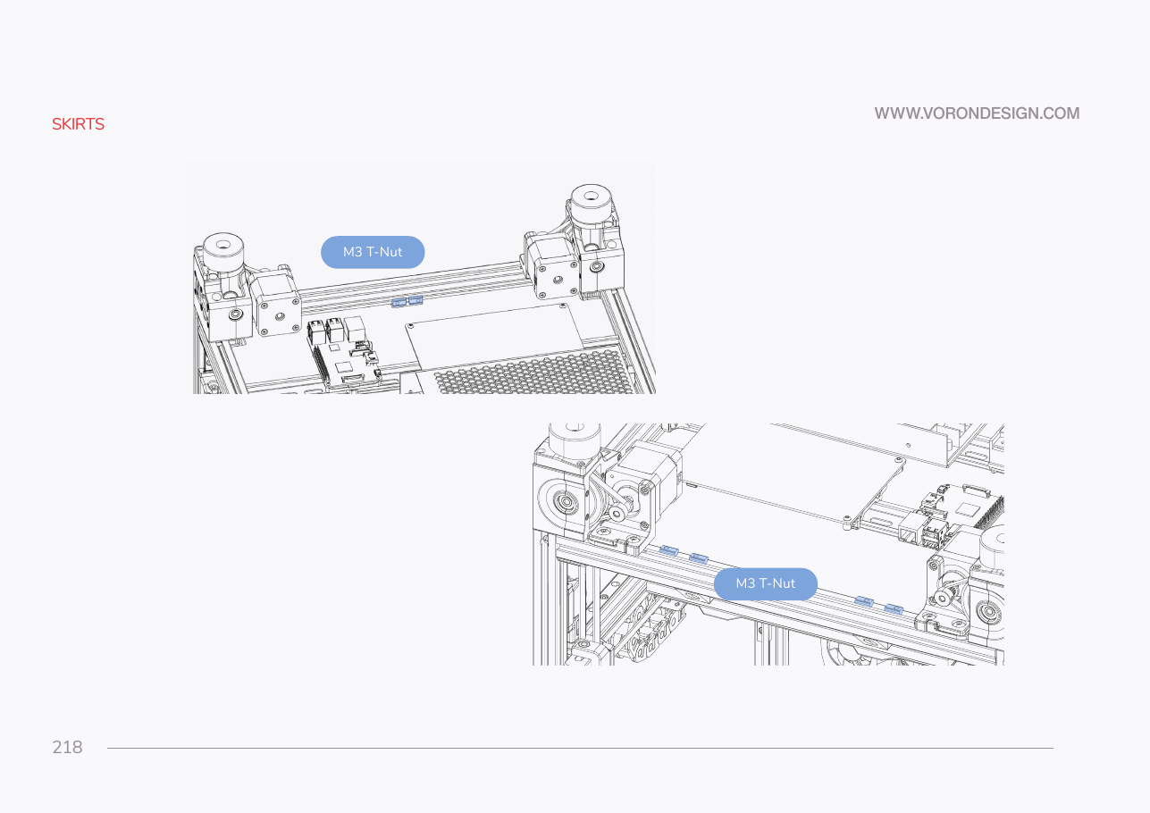 Step 11.12Pre-load the skirt T-nutswith a helper
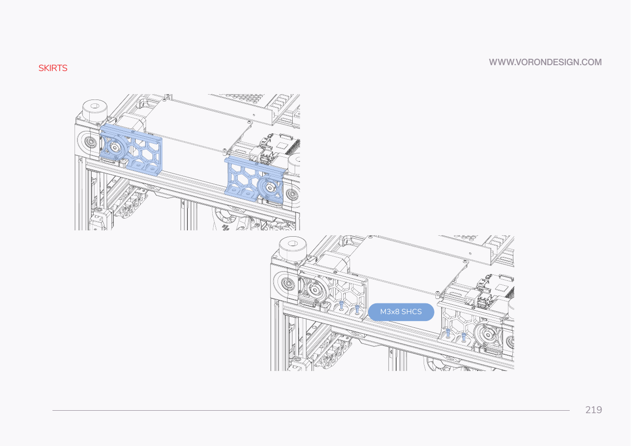 Step 11.13Mount the front skirt segmentswith a helper
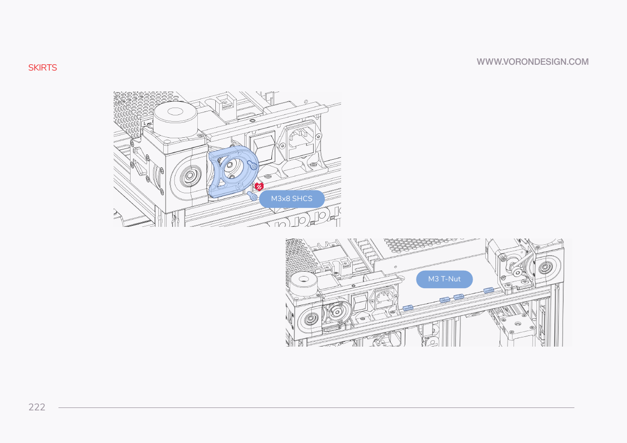 Step 11.14Mount the rear skirt runwith a helper
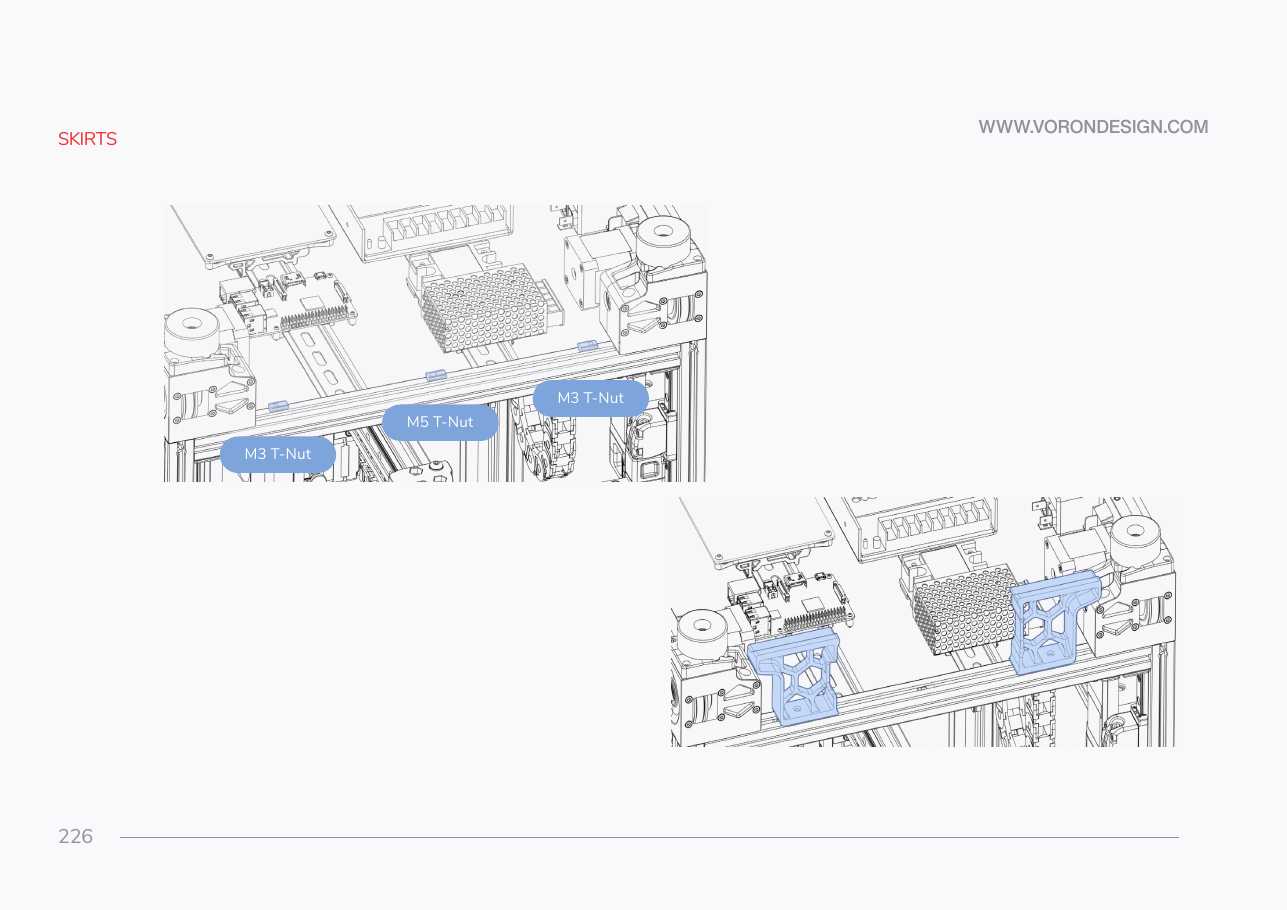 Step 11.15Mount the first side skirt runwith a helper
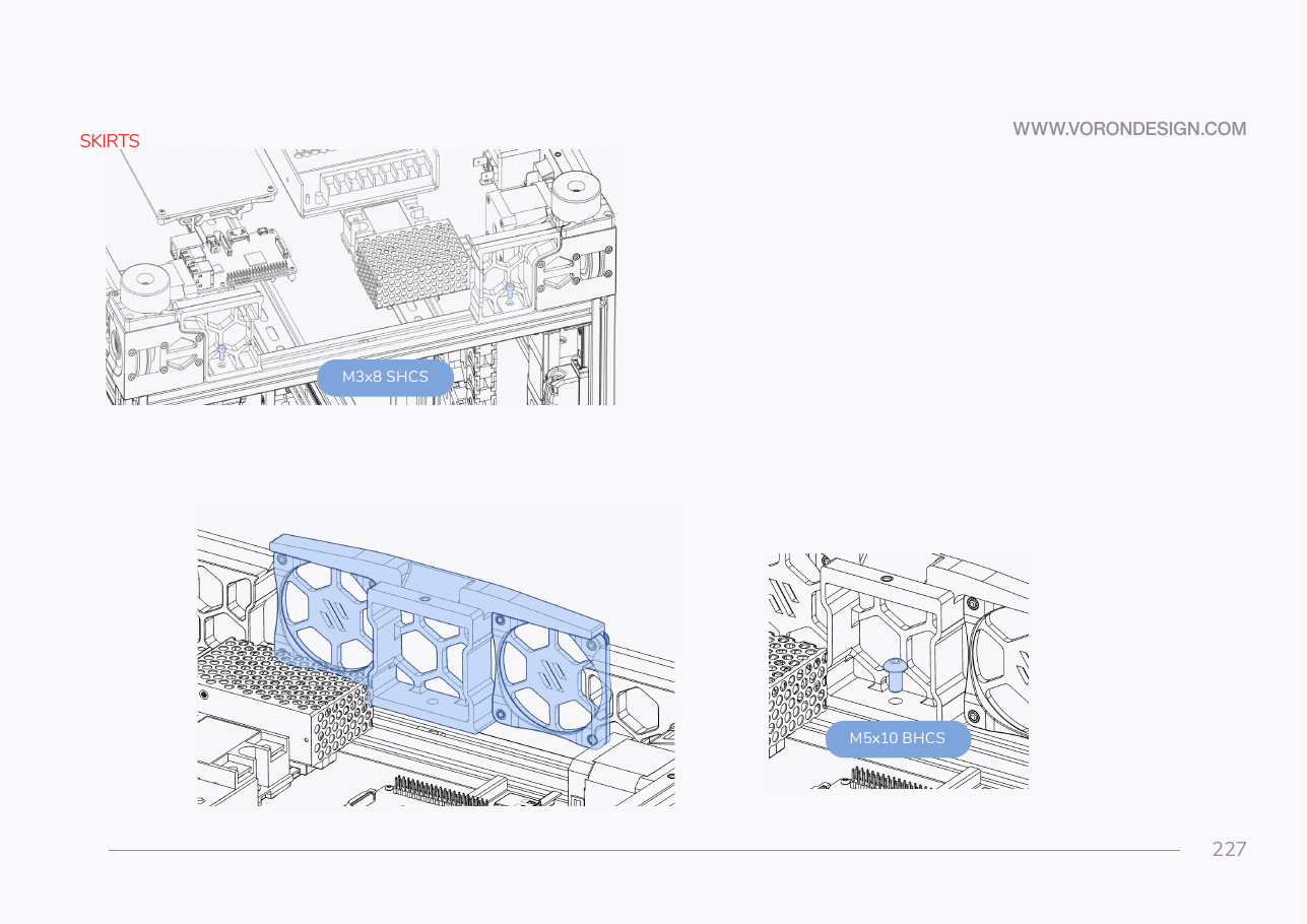 Step 11.16Drop in the fan module and close the side runwith a helper
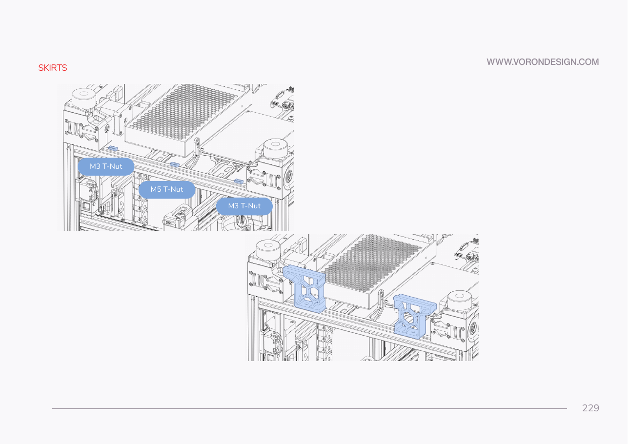 Step 11.17Mount the second side skirt runwith a helper
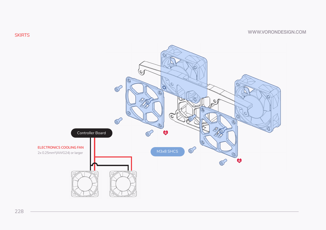 Step 11.18Verify the bay-fan wiring
Step 11.19Fit the bestagon insert (optional)with a helper
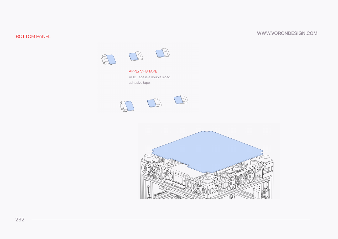 Step 11.20VHB the bottom-panel clips and hingeswith a helper
Step 11.21Fit the bottom panelwith a helper
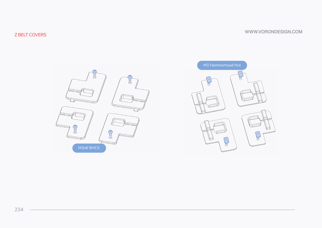 Step 11.22Choose the Z belt cover variant
Step 11.23Load each cover with a hammerhead nutwith a helper
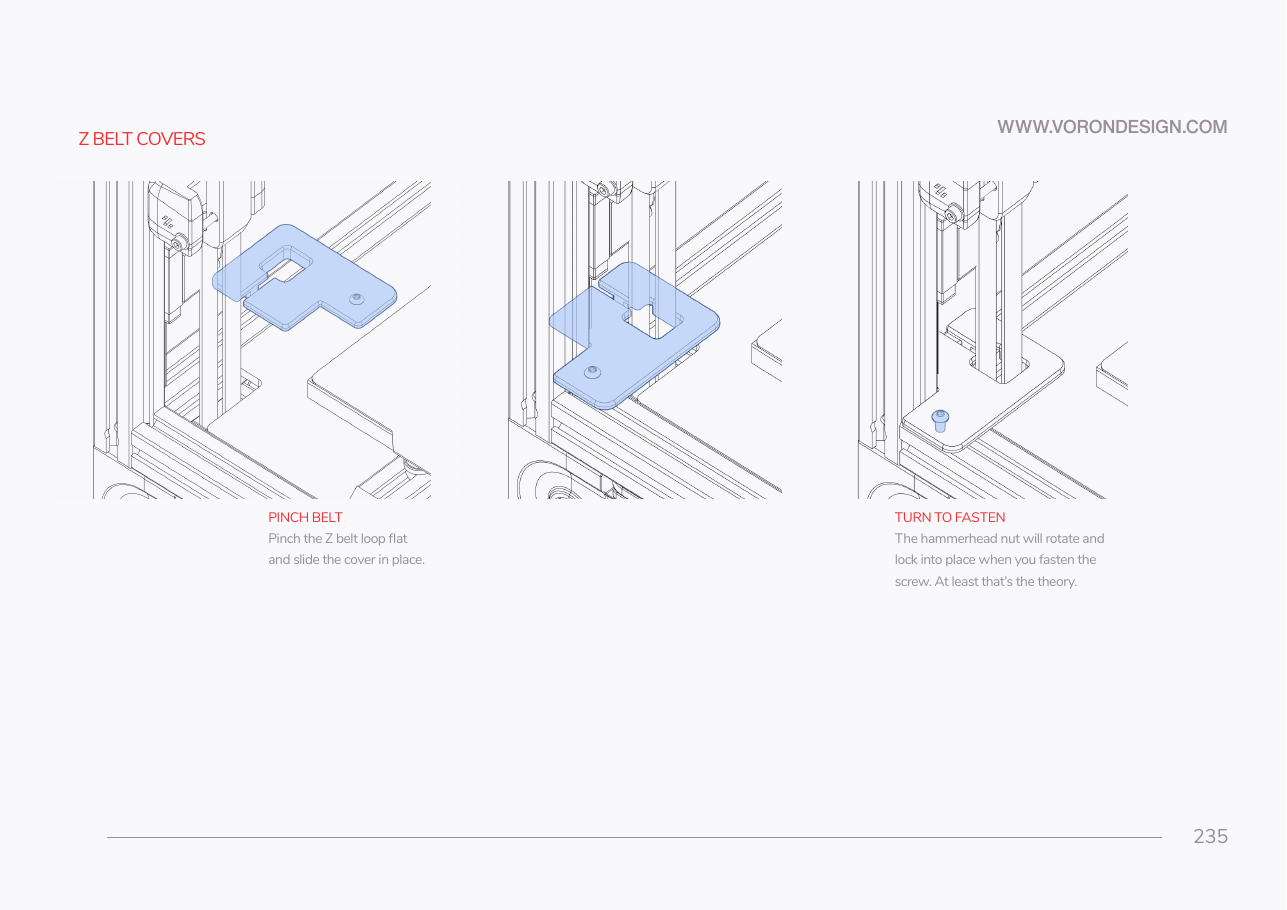 Step 11.24Fit the first Z belt coverwith a helper
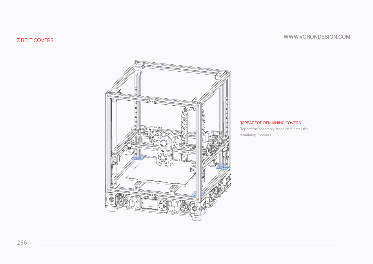 Step 11.25Fit the remaining three Z belt coverswith a helper
Step 11.26Break out the Nevermore printed supports
Step 11.27Modify both 5015 fan enclosures
Step 11.28Heat-set the Nevermore parts
Step 11.29Cut the connector off the long-wire fan
Step 11.30Fit the first fan into the plenum
Step 11.31Fit the second fan and trim the leads
Step 11.32Bolt the fans to the plenum
Step 11.33Solder the fans to the bridge PCB
Step 11.34Glue the plenum magnetswith a helper
Step 11.35Close the plenum lid
Step 11.36Glue the cartridge magnets to matchwith a helper
Step 11.37Fill and close the cartridgewith a helper
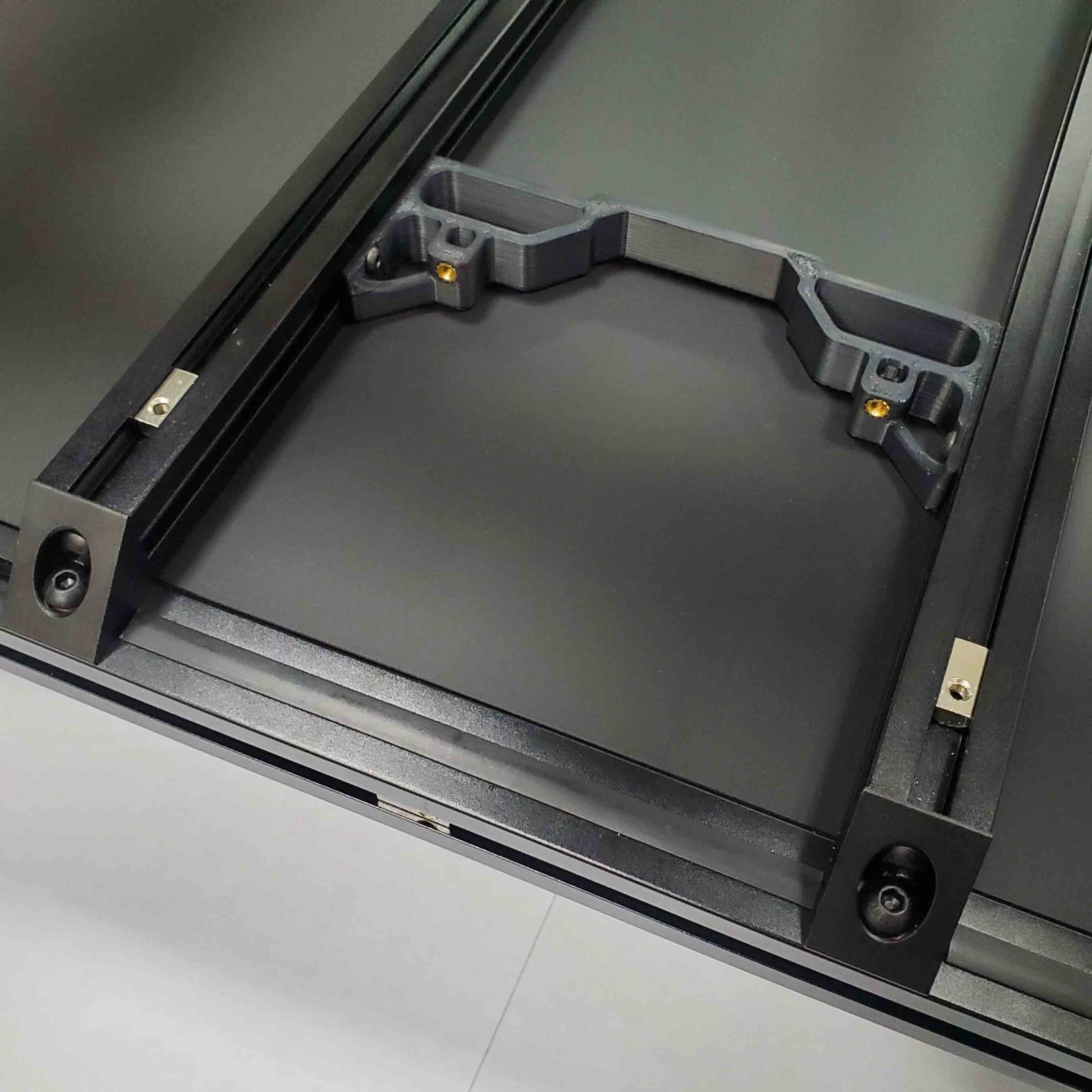 Step 11.38Mount the plenum in the chamber
Step 11.39Attach the cartridge
Step 11.40Connect the filter fanwith a helper
Step 11.41Note the filter fan config for Ch 12with a helper
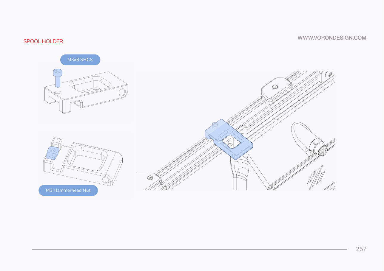 Step 11.42Fit the bowden retainer
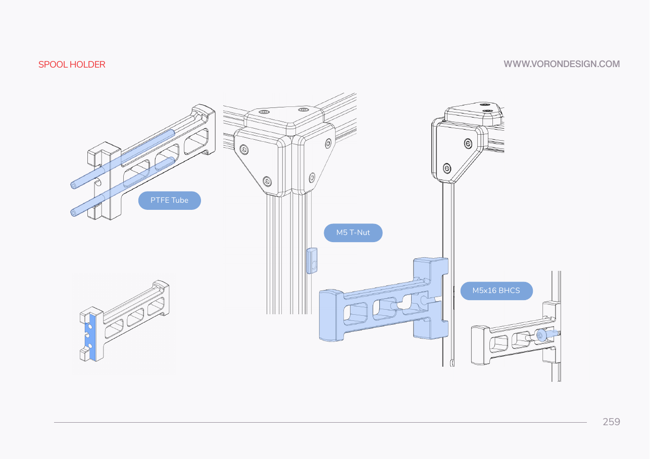 Step 11.43Fit the spool holder arm
Step 11.44Assemble the Clicky-Clack door framewith a helper
Step 11.45Fit the rubber panel retainer strip
Step 11.46Build the door hinges: dowel into the solid halves
Step 11.47Bush the sleeve halves
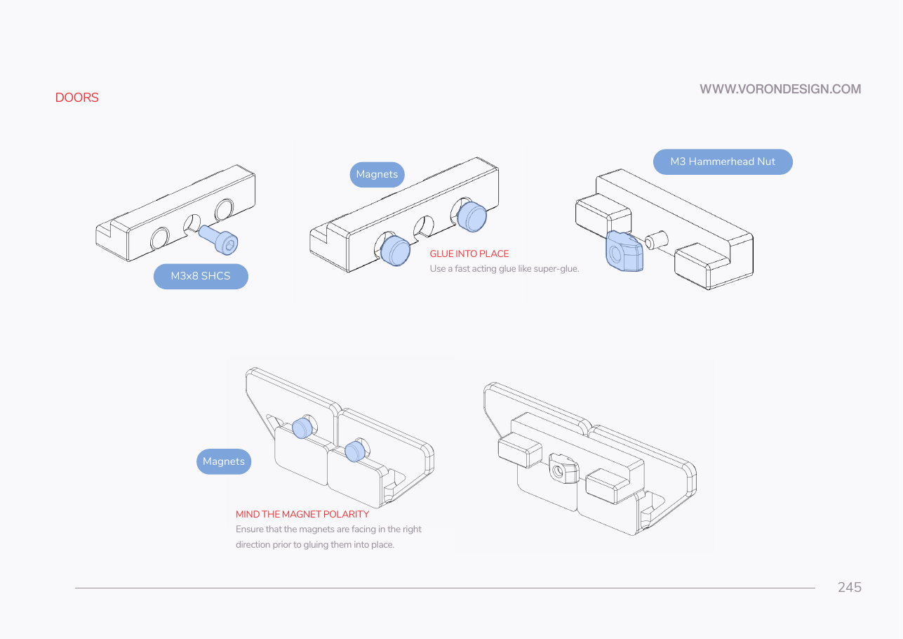
Step 11.48Glue the handle, latch and handle-hinge magnetswith a helper
Step 11.49Fit the latch's heat-set and panel clip
Step 11.51Foam-tape the front openingwith a helper
Note⛔ Stop here until Ch 13 is complete
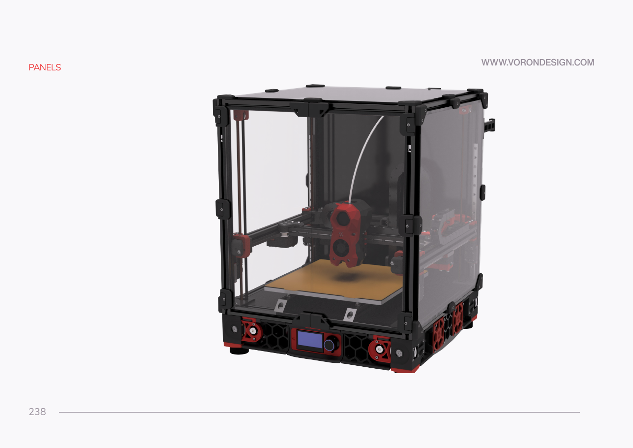 Step 11.52Foam-tape the back panelwith a helper
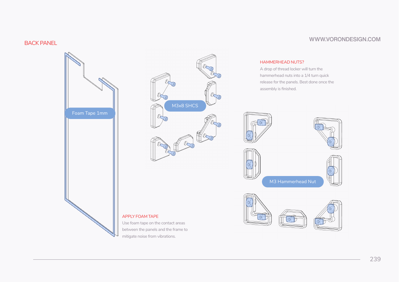 Step 11.53Fit the back-panel clipswith a helper
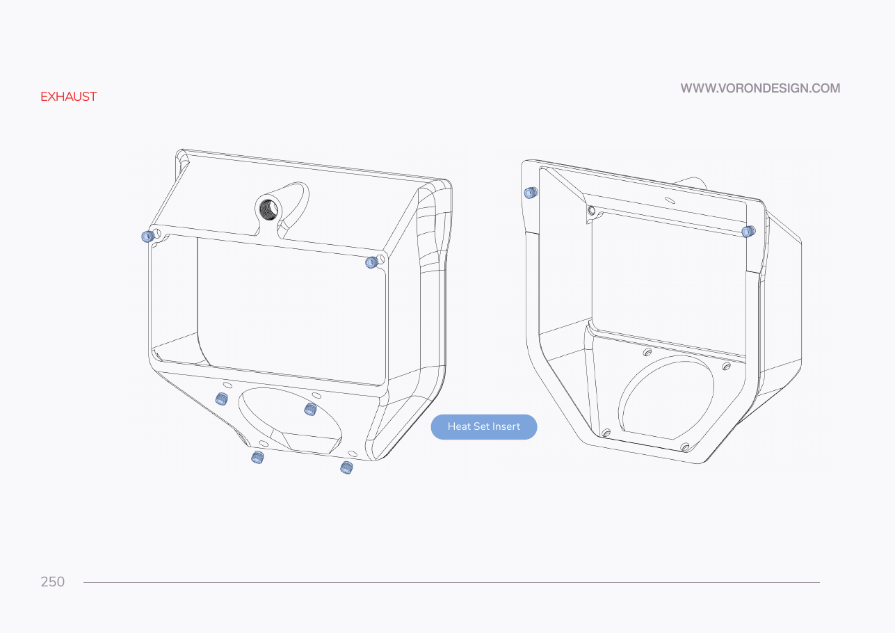 Step 11.54Fit the exhaust cover and grill
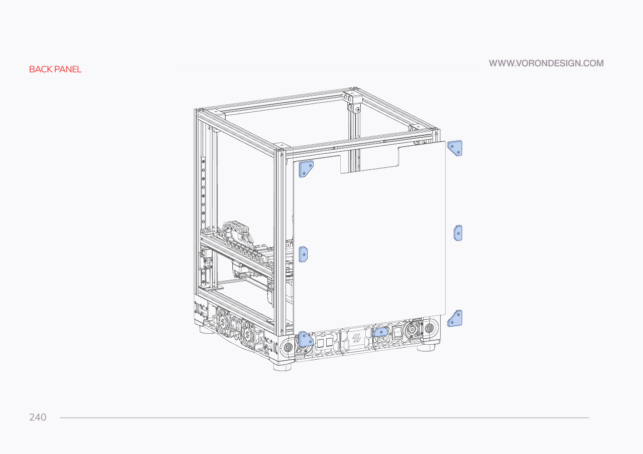 Step 11.55Hang the back panelwith a helper
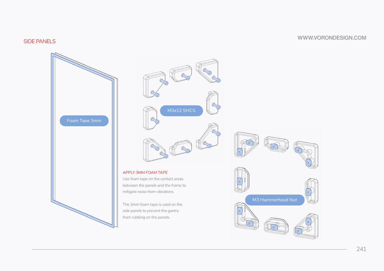 Step 11.56Foam-tape the side panelswith a helper
Step 11.57Fit the first side panelwith a helper
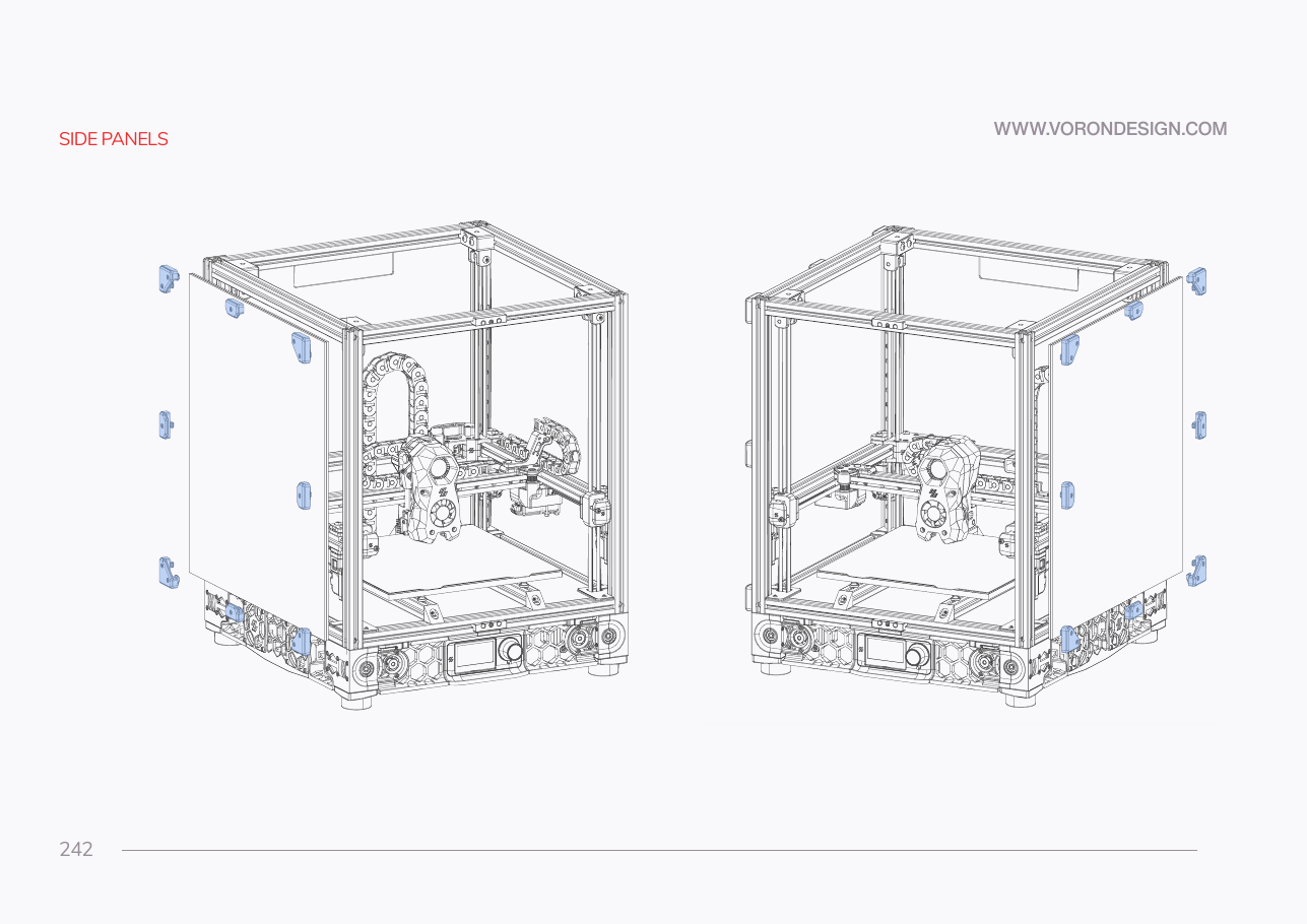 Step 11.58Fit the second side panelwith a helper
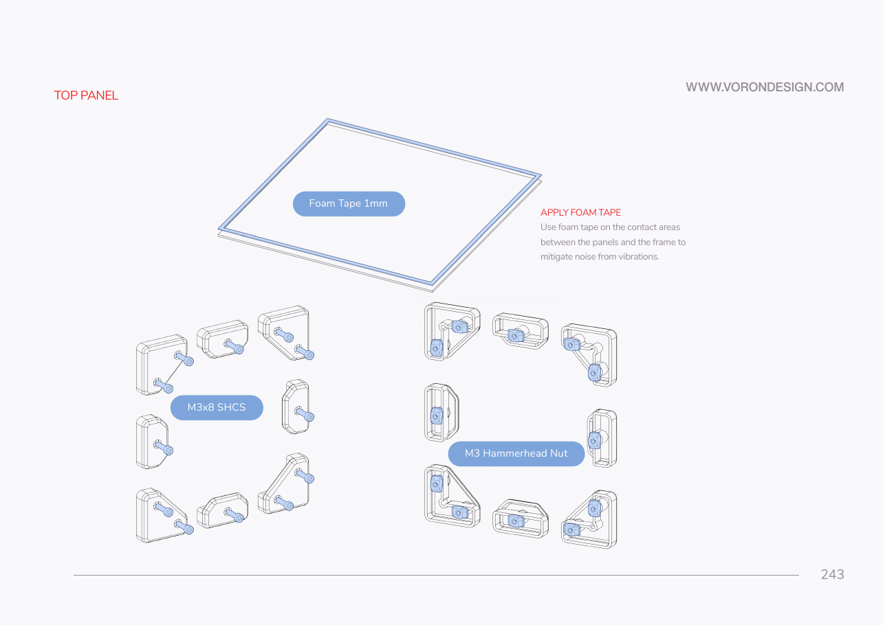 Step 11.59Fit the top panelwith a helper
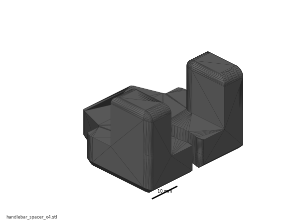 Step 11.60Fit the aluminium handlebarswith a helper
 Step 11.61Do not fit the stock doorswith a helper
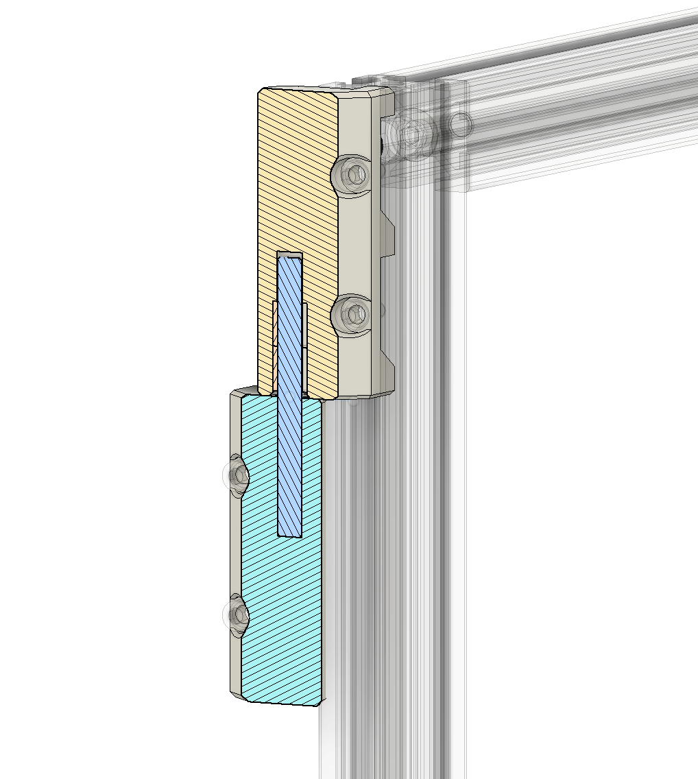 Step 11.62Hang the door hingeswith a helper
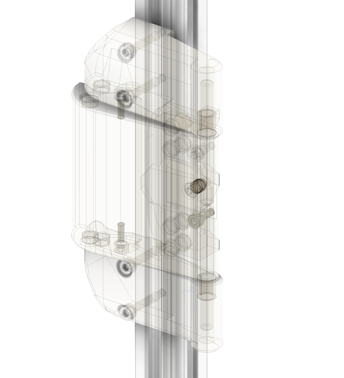 Step 11.64Fit the handle and align the doorwith a helper
Step 11.65Thread-lock the hammerhead nuts
Gather per session — what to lay out before each bench segment.
- Steps 11.67–11.4 · ~25 min — Fasteners, Tools & Misc box: M3×5×4 heat-set insert ×27 · Printed parts:
[a]_fan_grill_retainer×2 (bin 11-fans);front_skirt_a_350×1 (bin 11-skirts);front_skirt_b_350×1 (bin 11-skirts);rear_center_skirt_350×1 (bin 11-skirts);keystone_panel×1 (bin 11-skirts);side_skirt_a_350×2 (bin 11-skirts);side_skirt_b_350×2 (bin 11-skirts);side_fan_support×2 (bin 11-skirts) · Tools and consumables: multimeter · Already on the bench: the BTTmount, taped to the front extrusion (bin 10-tft);power_inlet_IECGS_1mm, already on the frame (bin 09-bay); the two bay fans - Steps 11.5–11.8 · ~10 min — Electronics 1 box: 4.3" capacitive DSI display ×1 · Fasteners, Tools & Misc box: M3×5×4 heat-set insert ×2; M3×8 SHCS ×5; M3 roll-in T-nut ×3 · BTT screen packaging: FFC ribbon ×1; M2.5×6 screw ×4 · Printed parts:
mount×1 (bin 10-tft);[a]_faceplate×1 (bin 10-tft) · Already on the bench: the faceplatedmount(bin 10-tft); the touchscreen module, ribbon latched at both ends; the FFC ribbon, Pi end contacts forward and blue tab rearward - Steps 11.9–11.12 · ~15 min — Fasteners, Tools & Misc box: M3×8 SHCS ×22; M3 roll-in T-nut ×12; M5 roll-in T-nut ×2 · Printed parts:
[a]_belt_guard_a×2 (bin 11-fans);[a]_belt_guard_b×2 (bin 11-fans);[a]_fan_grill_a×2 (bin 11-fans);[a]_fan_grill_b×2 (bin 11-fans);keystone_panel×1 (bin 11-skirts);[a]_keystone_blank_insert×1 (bin 11-skirts);side_fan_support×2 (bin 11-skirts) · Already on the bench: the CAT6 keystone insert; the two bay fans, inserts fitted; the two grill retainers, inserts fitted - Steps 11.13–11.17 · ~20 min — Fasteners, Tools & Misc box: M3×8 SHCS ×14; M5×10 BHCS ×2 · Printed parts:
front_skirt_a_350×1 (bin 11-skirts);front_skirt_b_350×1 (bin 11-skirts);rear_center_skirt_350×1 (bin 11-skirts);side_skirt_a_350×2 (bin 11-skirts);side_skirt_b_350×2 (bin 11-skirts) · Already on the bench: the four front T-nuts; the fourth belt guard; the populatedkeystone_panel(bin 11-skirts);power_inlet_IECGS_1mm, already on the frame (bin 09-bay); the four rear T-nuts; this side's two M3 T-nuts; the right-hand fan support with both fans; this side's M5 T-nut; the left-hand fan support with its retainers; this side's three T-nuts - Steps 11.18–11.21 · ~20 min — Fasteners, Tools & Misc box: M3×8 SHCS ×6 · Panel Kit box (carton 2): bottom panel, acrylic, black, 469×469×4 mm ×1 · Printed parts:
bottom_panel_clip×4 (bin 11-panels);bottom_panel_hinge×2 (bin 11-panels);ldo_bestagon_insert×1 (bin 11-skirts) · Tools and consumables: 3M VHB tape, six pads; IPA and a lint-free cloth · Already on the bench: the 3×2 XH splicer PCB on its printed spacer; the six taped clips and hinges - Steps 11.22–11.25 · ~15 min — Fasteners, Tools & Misc box: M3 hammerhead T-nut ×4; M3×6 BHCS ×4 · Printed parts:
z_belt_cover_a×2 (bin 11-panels);z_belt_cover_b×2 (bin 11-panels) · Already on the bench: the four Z belt covers; one loaded Z belt cover; the three remaining loaded covers - Steps 11.26–11.29 · ~15 min — Fasteners, Tools & Misc box: M3×5×4 heat-set insert ×6 · Printed parts:
V2_Duo_Plenum×1 (bin 11-nevermore);V2_Duo_Plenum_LID×1 (bin 11-nevermore);Regular_Cartridge×1 (bin 11-nevermore);Regular_Cartridge_Lid×1 (bin 11-nevermore) · Tools and consumables: wire snips; side cutters · Set out for later steps: Nevermore 5015 fan ×2 · Already on the bench: the plenum and the cartridge - Steps 11.30–11.33 · ~20 min — Belts, Chains & Fans box: Nevermore 5015 fan, cut lead ×3 · The Nevermore parts bag: M3×16 BHCS ×4 · Tools and consumables: tweezers; side cutters; soldering iron and solder; multimeter · Already on the bench: the plenum; the two Nevermore fans; the saved connector pigtail
- Steps 11.34–11.37 · ~20 min — Fasteners, Tools & Misc box: 6×3 mm neodymium magnet ×8; M3×6 BHCS ×2 · Printed parts:
V2_Duo_Plenum_LID×1 (bin 11-nevermore);Regular_Cartridge_Lid×1 (bin 11-nevermore) · Tools and consumables: super glue; a marker; 4 mm acid-free activated carbon pellets, not supplied - Steps 11.38–11.43 · ~15 min — Fasteners, Tools & Misc box: M3 roll-in T-nut ×2; M3×12 SHCS ×2; M3 hammerhead T-nut ×1; M3×8 SHCS ×1; M5 roll-in T-nut ×1; M5×16 BHCS ×1 · Printed parts:
bowden_retainer×1 (bin 11-spool);spool_holder×1 (bin 11-spool) · Tools and consumables: PTFE tube, 4 mm OD, 3 mm ID, 1.2 m; PTFE tube, the two 86 mm lengths · Already on the bench: the plenum assembly; the cartridge; the kit's FILTER FAN extension lead - Steps 11.44–11.47 · ~20 min — Clicky-Clack acrylic panel: door panel, acrylic, 480×500×3 mm ×1 · Clicky-Clack door kit: door frame extrusion, 470 mm ×2; door frame extrusion, 530 mm ×2; M5×16 BHCS ×4; panel retainer strip, 2 m ×1; M5×45 dowel pin ×2; M5×7×8 split bushing ×4 · Printed parts:
Hinge-L-solid×2 (bin 11-door);Hinge-L-sleeve×2 (bin 11-door) · Tools and consumables: machinist square; side cutters; small hammer - Steps 11.48–11.51 · ~20 min — Clicky-Clack door kit: 6×3 mm magnet ×12; M3×5×4 heat-set insert ×1; M3×8 BHCS ×1; M5×45 dowel pin ×2; M5×7×8 split bushing ×2; M3×8 SHCS ×2 · Printed parts:
Handle×1 (bin 11-door);Latch×1 (bin 11-door);Handle-Hinge_Top×1 (bin 11-door);Handle-Hinge_Bottom×1 (bin 11-door);Panel_Clip×1 (bin 11-door) · Tools and consumables: super glue; 3 mm foam tape · Already on the bench: the latch; the handle and both handle hinges - Steps 11.52–11.55 · ~25 min — Motion box: 4mm Bowden Coupler ×1 · Fasteners, Tools & Misc box: M3×8 SHCS ×11; M3 hammerhead T-nut ×11; M3×12 SHCS ×2; M3 heat-set insert ×2; M5 roll-in T-nut ×2; M5×10 BHCS ×2 · Panel Kit box (carton 2): back panel, acrylic, black, 483×503×3 mm ×1 · Printed parts:
corner_panel_clip_4mm×4 (bin 11-clips-4mm);midspan_panel_clip_4mm×3 (bin 11-clips-4mm);exhaust_cover×1 (bin 11-finish);exhaust_filter_grill×1 (bin 11-finish);CMD_V2_6B_154mm_DUCT_COVER×2 (bin 11-lids-DC);CMD_V2_6B_90DEG_COVER×2 (bin 11-lids-DC);V2L_90DEG_COVER_MIRROR×1 (bin 11-lids-DC);V2L_58mm_DUCT_COVER×3 (bin 11-lids-DC);V2L_130mm_DUCT_COVER×1 (bin 11-lids-DC);V2L_70mm_DUCT_COVER×1 (bin 11-lids-DC);CMD_Remix-V3_DUCT-2B_45deg_LID×2 (bin 11-lids-DC);V3L_10mm_DUCT_COVER×1 (bin 11-lids-DC, 10-lids-AC);V3L_154N_DUCT_COVER×2 (bin 11-lids-DC);V3L_T_REG_N_COVER×2 (bin 11-lids-DC) · Tools and consumables: 1 mm foam tape; soldering iron with the LDO insert tip · Already on the bench: the back-panel clips, exhaust cover and grill; the reverse-bowden PTFE - Steps 11.56–11.58 · ~25 min — Fasteners, Tools & Misc box: M3×12 SHCS ×24; M3 hammerhead T-nut ×24 · Panel Kit box (carton 2): side panel, PC, clear, 483×503×3 mm ×2 · Printed parts:
corner_panel_clip_6mm×8 (bin 11-clips-6mm);midspan_panel_clip_6mm×8 (bin 11-clips-6mm) · Tools and consumables: 3 mm foam tape; a lint-free cloth - Steps 11.59–11.61 · ~15 min — Fasteners, Tools & Misc box: M3×8 SHCS ×12; M3 hammerhead T-nut ×12; aluminium handle (LDO) ×2; M5×14 BHCS ×4; M5 hammerhead T-nut ×4 · Panel Kit box (carton 2): top panel, PC, clear, 483×483×3 mm ×1 · Printed parts:
corner_panel_clip_4mm×4 (bin 11-clips-4mm);midspan_panel_clip_4mm×4 (bin 11-clips-4mm);handlebar_spacer_x4(batch B07) ×4 (bin 11-finish) · Tools and consumables: 1 mm foam tape - Steps 11.62–11.64 · ~25 min — Clicky-Clack door kit: M3×8 SHCS ×8; M3 roll-in T-nut ×12; M3×20 SHCS ×4 · Tools and consumables: blue tape; a paper shim · Already on the bench: the two door hinges; the latch with its panel clip; the hammerhead nut of the midspan clip it displaces; the handle assembly
- Steps 11.65–11.66 · ~15 min — Tools and consumables: thread locker, optional; 6 mm extrusion slot cover, optional