Chapter 04 — A/B drive units and front idlers
Start the chapter · Resume · Read the whole chapter on one page
Before — end of Ch 03: the bed
After — end of Ch 04: the four bench assemblies
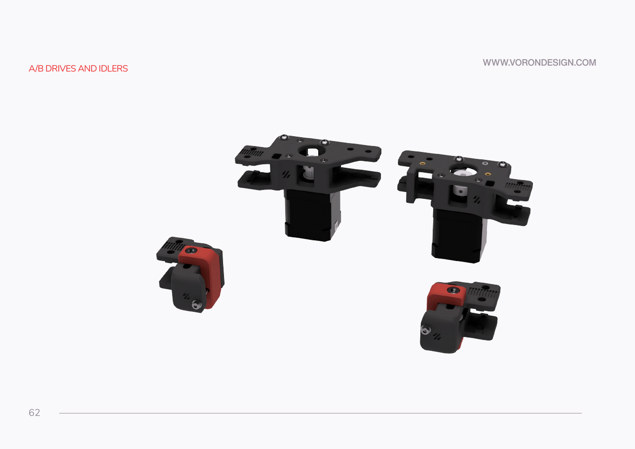 Step 04.1Lay the chapter out as four separate kitswith a helper
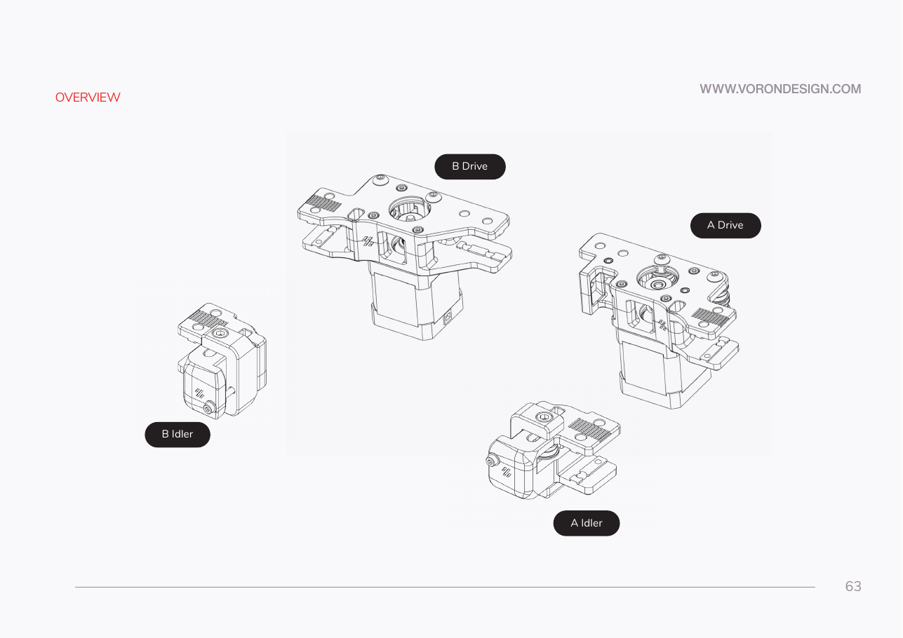 Step 04.2Fix which assembly is A and which is Bwith a helper
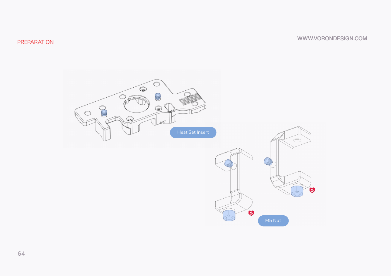 Step 04.3Heat-set the two inserts in a_drive_frame_upper
Step 04.4Heat-set one insert into each tension arm
Step 04.5Press an M5 nut into each tension arm foot
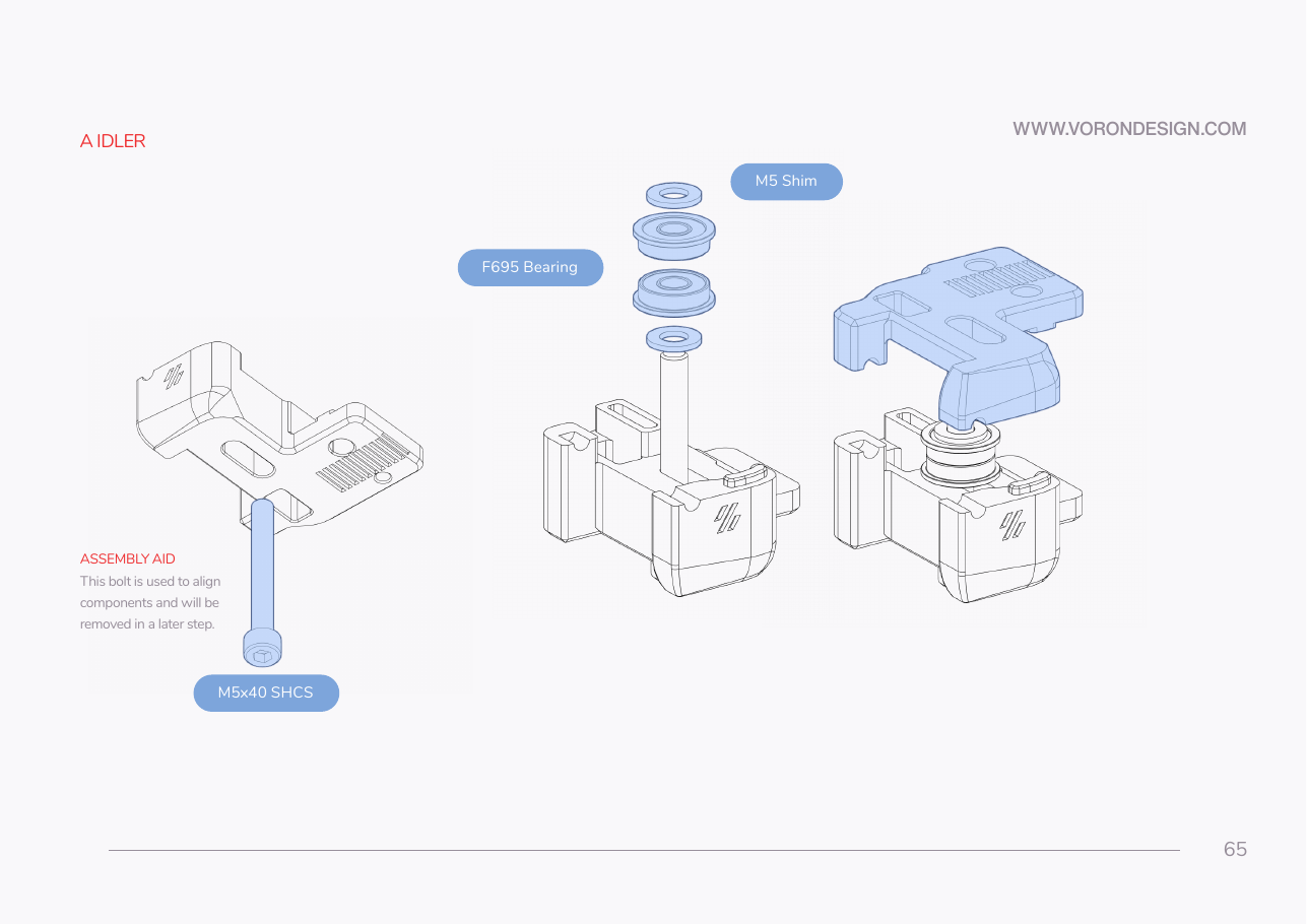 Step 04.6A idler: stand the assembly-aid bolt in the lower frame
Step 04.7A idler: build the bearing stack
Step 04.8A idler: cap the stack with the upper frame
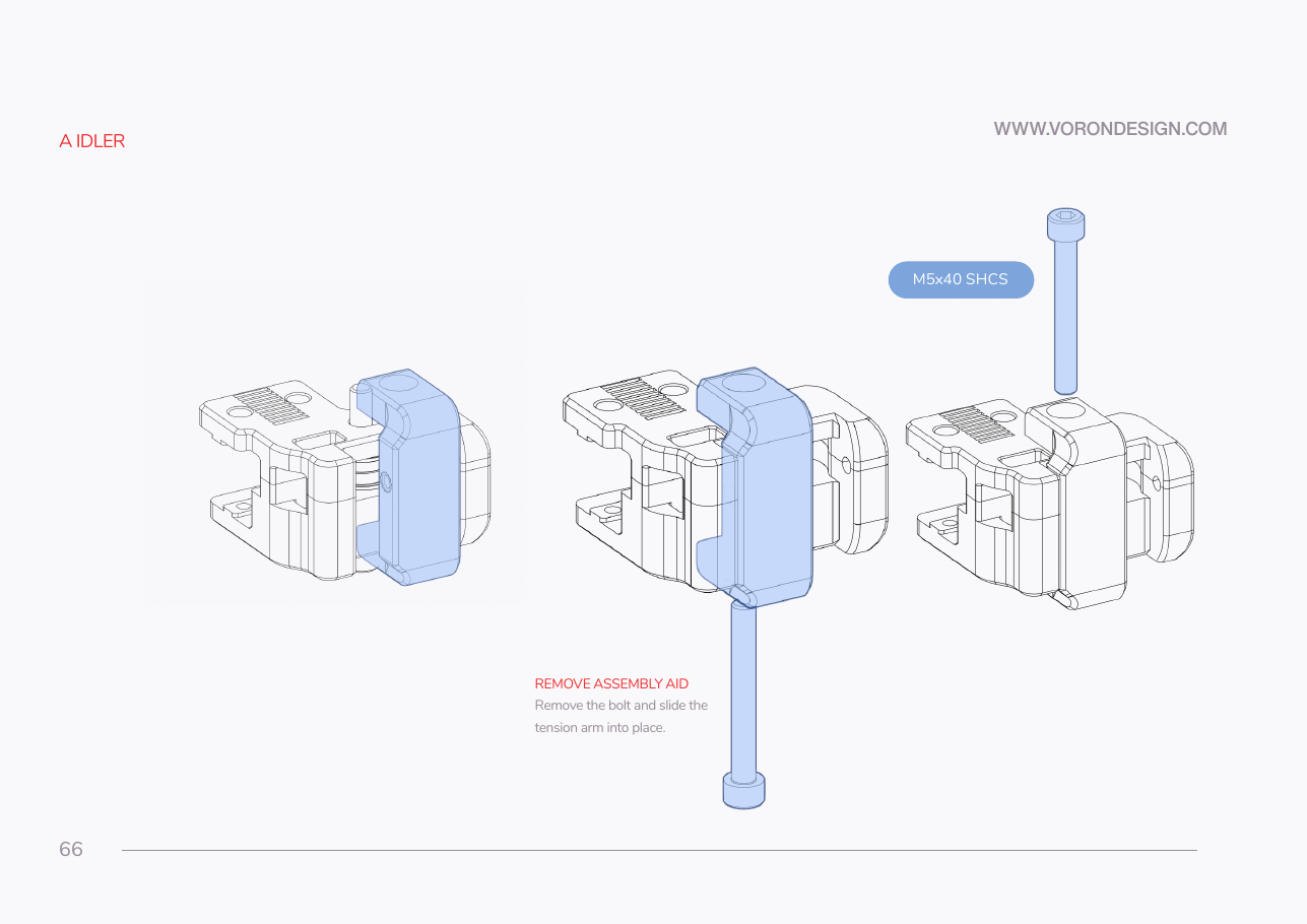 Step 04.9A idler: pull the aid bolt and slide in the tension armwith a helper
Step 04.10A idler: refit the M5×40 SHCS from the top
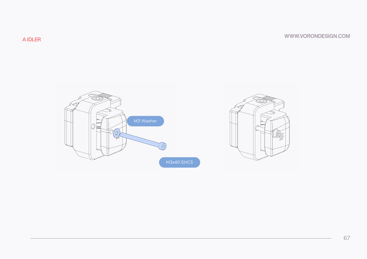 Step 04.11A idler: fit the M3 washer and M3×40 SHCS
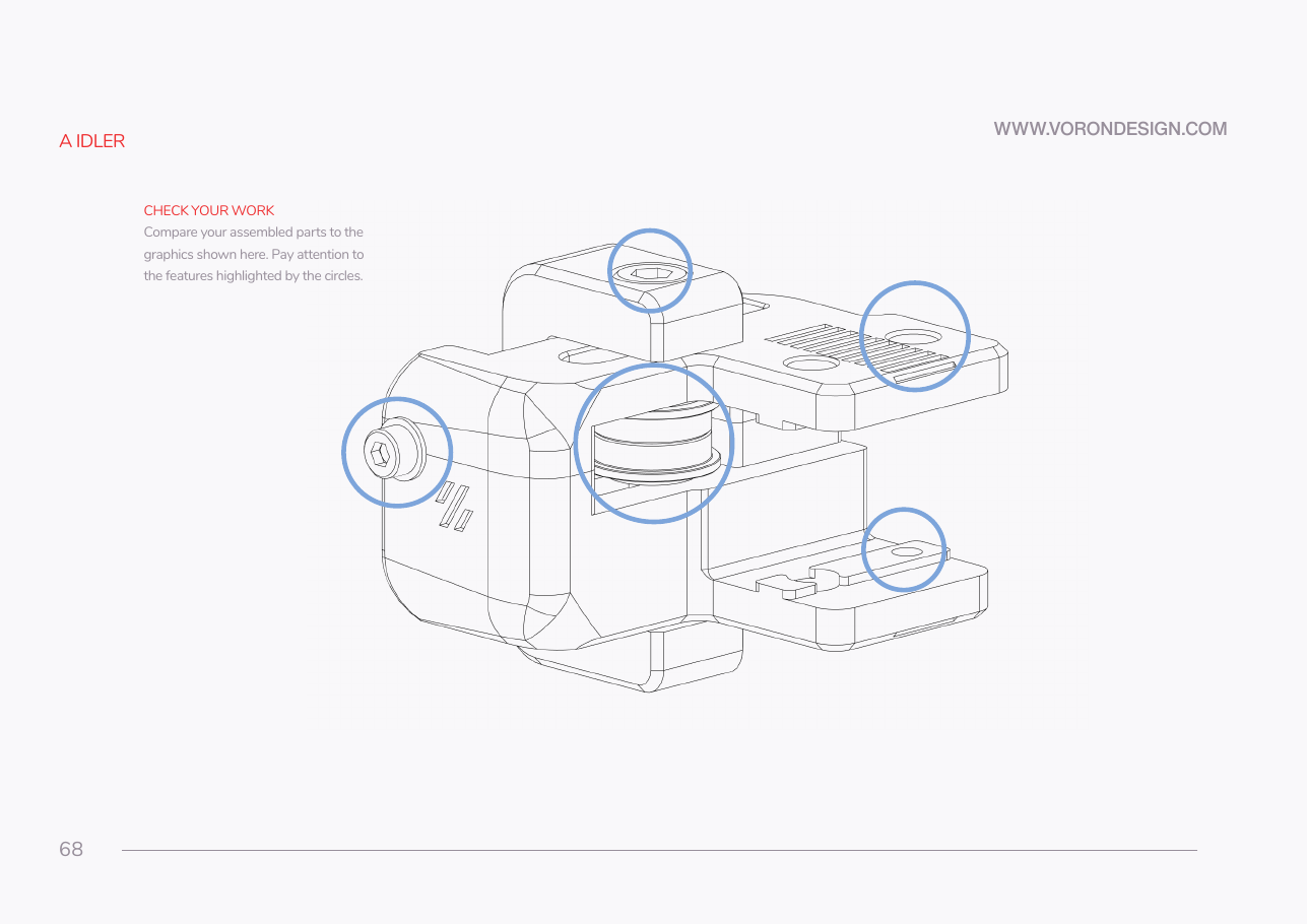 Step 04.12A idler: check your workwith a helper
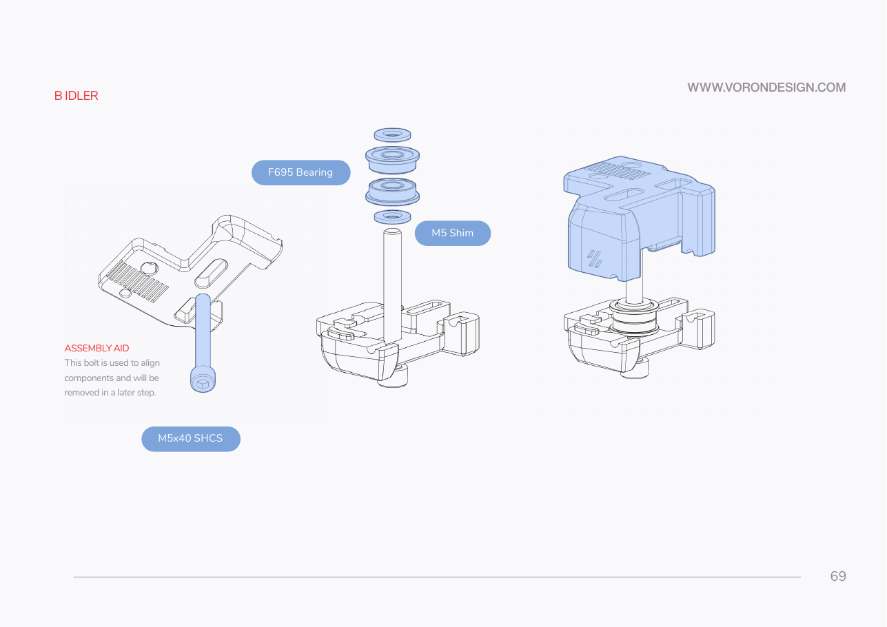 Step 04.13B idler: stand the assembly-aid bolt in the lower frame
Step 04.14B idler: build the bearing stack
Step 04.15B idler: cap the stack with the upper frame
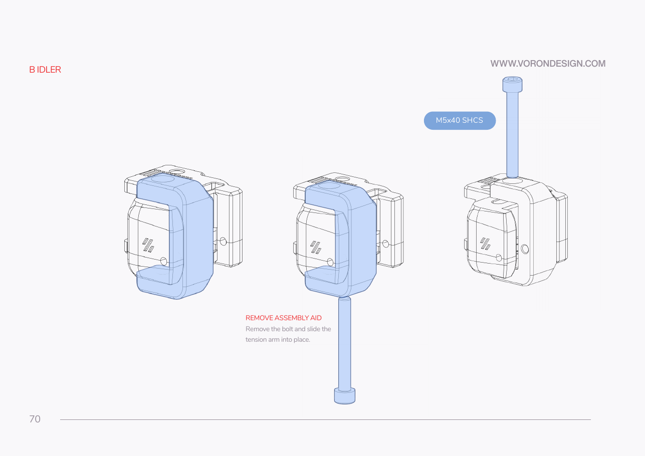 Step 04.16B idler: pull the aid bolt and slide in the tension armwith a helper
Step 04.17B idler: refit the M5×40 SHCS from the top
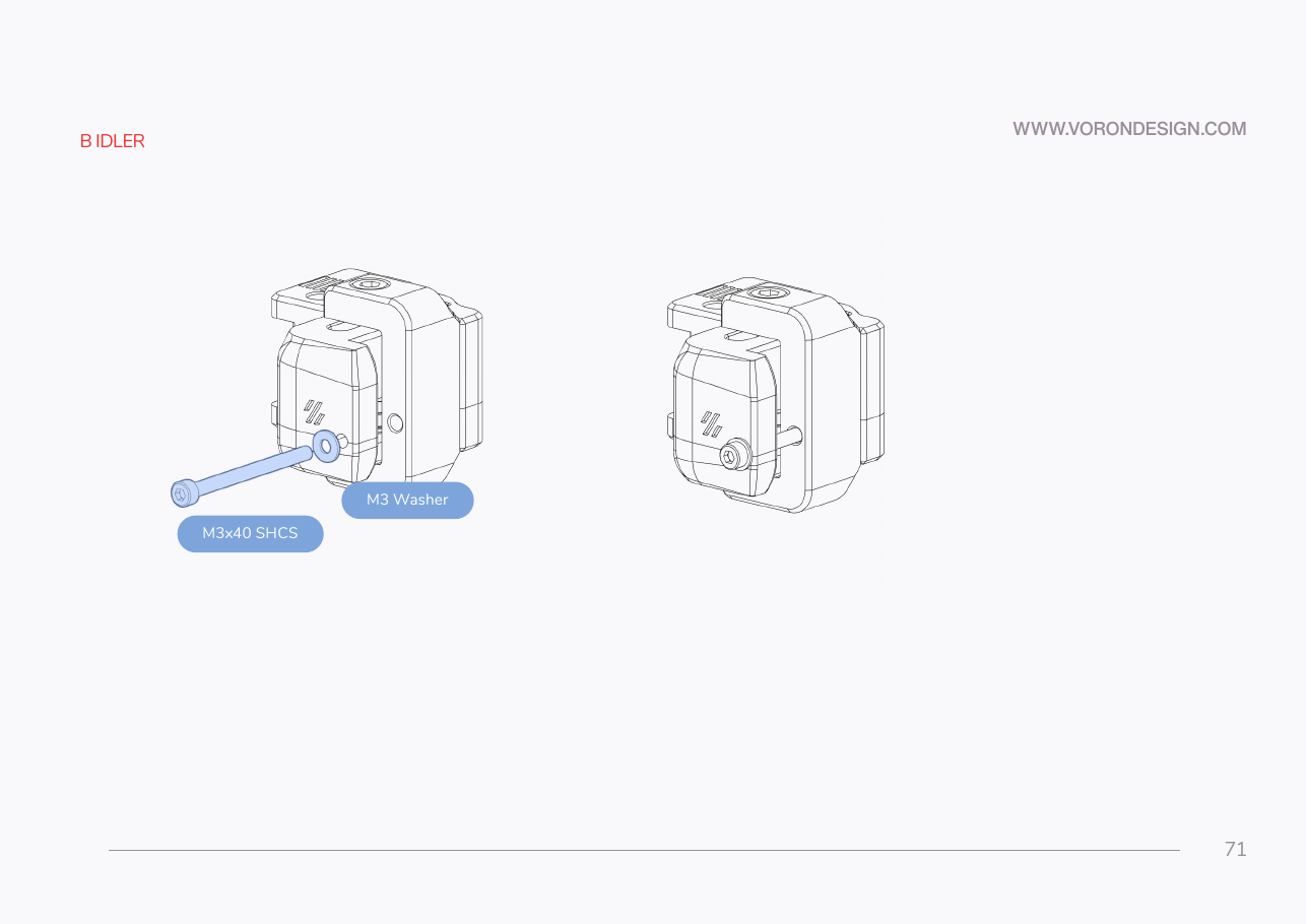 Step 04.18B idler: fit the M3 washer and M3×40 SHCS
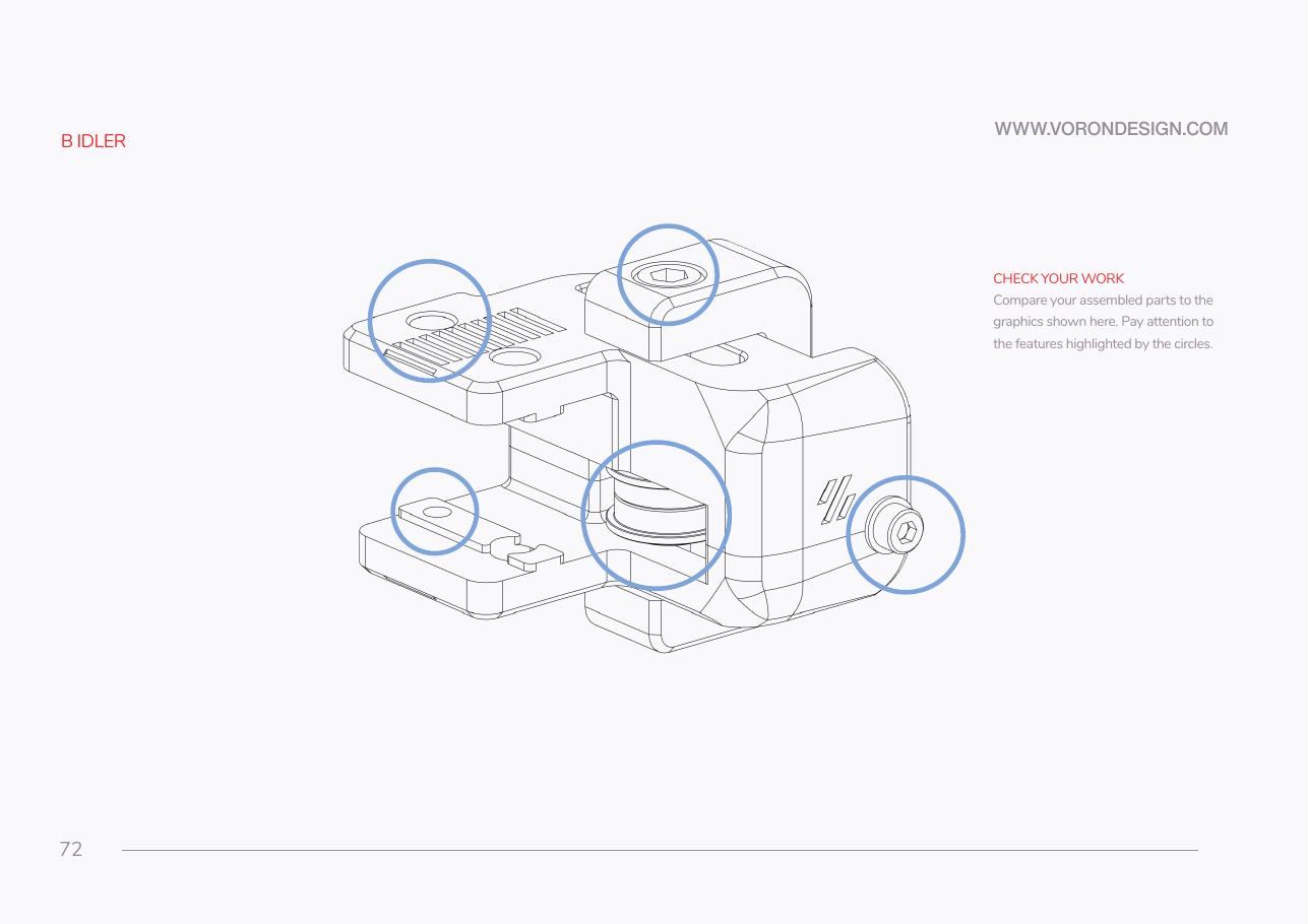 Step 04.19B idler: check your workwith a helper
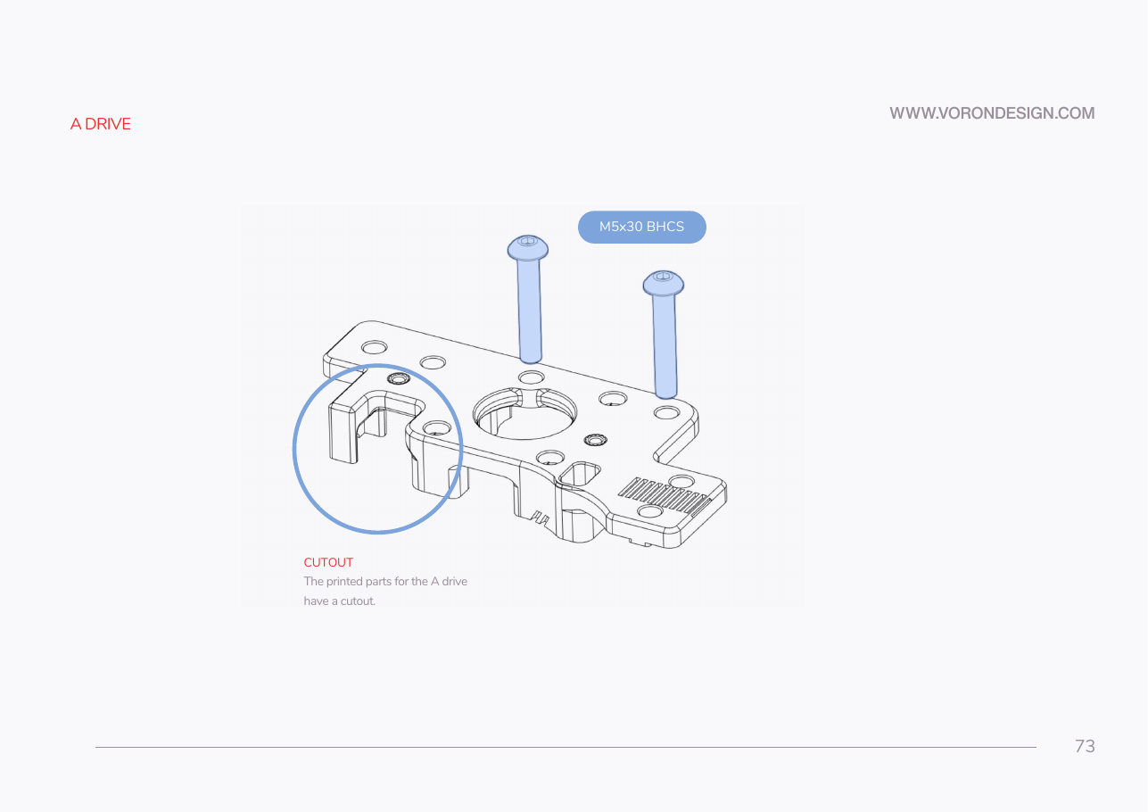 Step 04.20A drive: upper frame face down, two M5×30 BHCS
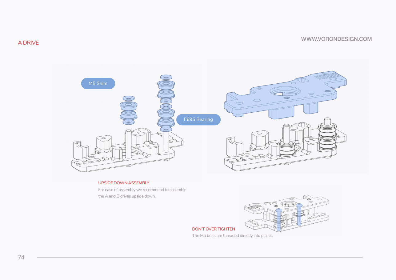 Step 04.21A drive: two-bearing stack on the near post
Step 04.22A drive: four-bearing stack on the far postwith a helper
Step 04.23A drive: close it with a_drive_frame_lower
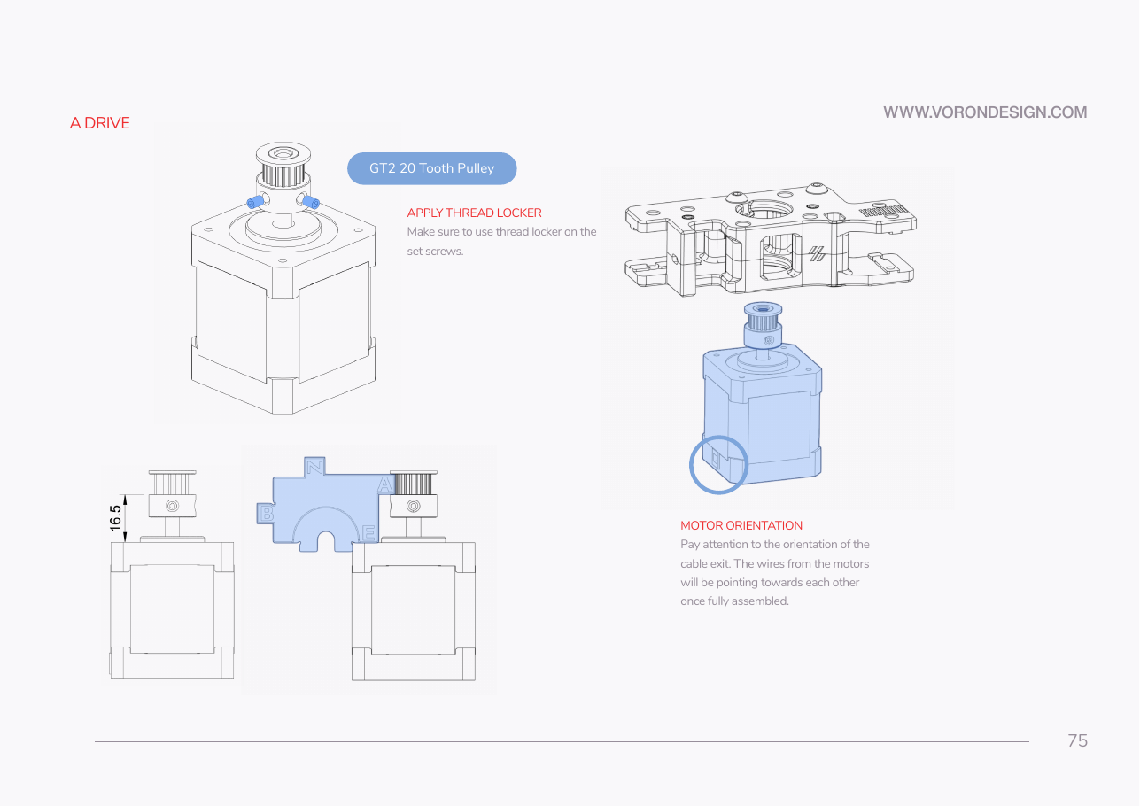 Step 04.24A drive: set the pulley on the A motor at 16.5 mmwith a helper
Step 04.25A drive: threadlock and lock the pulley set screws
Step 04.26A drive: offer the motor up with the cable exit inboard
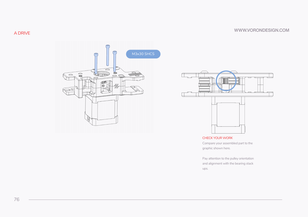 Step 04.27A drive: three M3×30 SHCS through the frames into the motor
Step 04.28A drive: check your work and the belt pathwith a helper
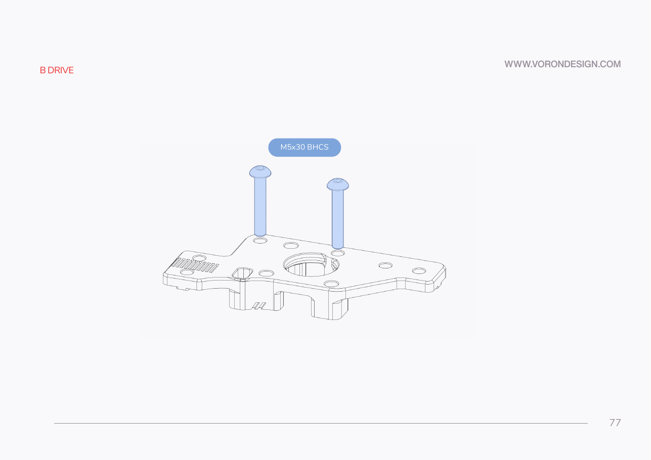 Step 04.29B drive: upper frame face down, two M5×30 BHCS
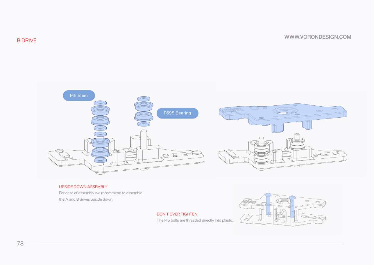 Step 04.30B drive: four-bearing stack on the far postwith a helper
Step 04.31B drive: two-bearing stack on the near post
Step 04.32B drive: close it with b_drive_frame_lower
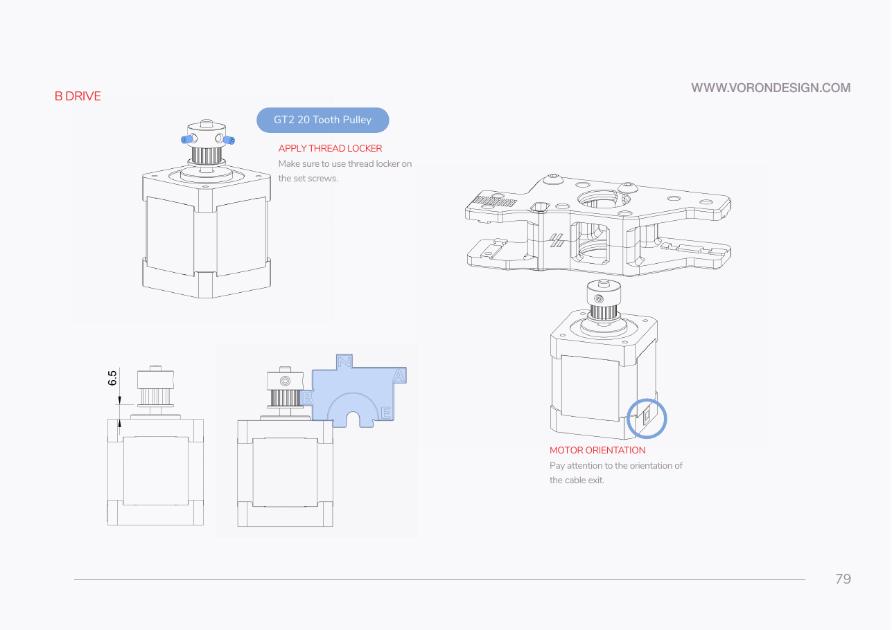 Step 04.33B drive: set the pulley on the B motor at 6.5 mm — flippedwith a helper
Step 04.34B drive: threadlock and lock the pulley set screws
Step 04.35B drive: offer the motor up with the cable exit inboardwith a helper
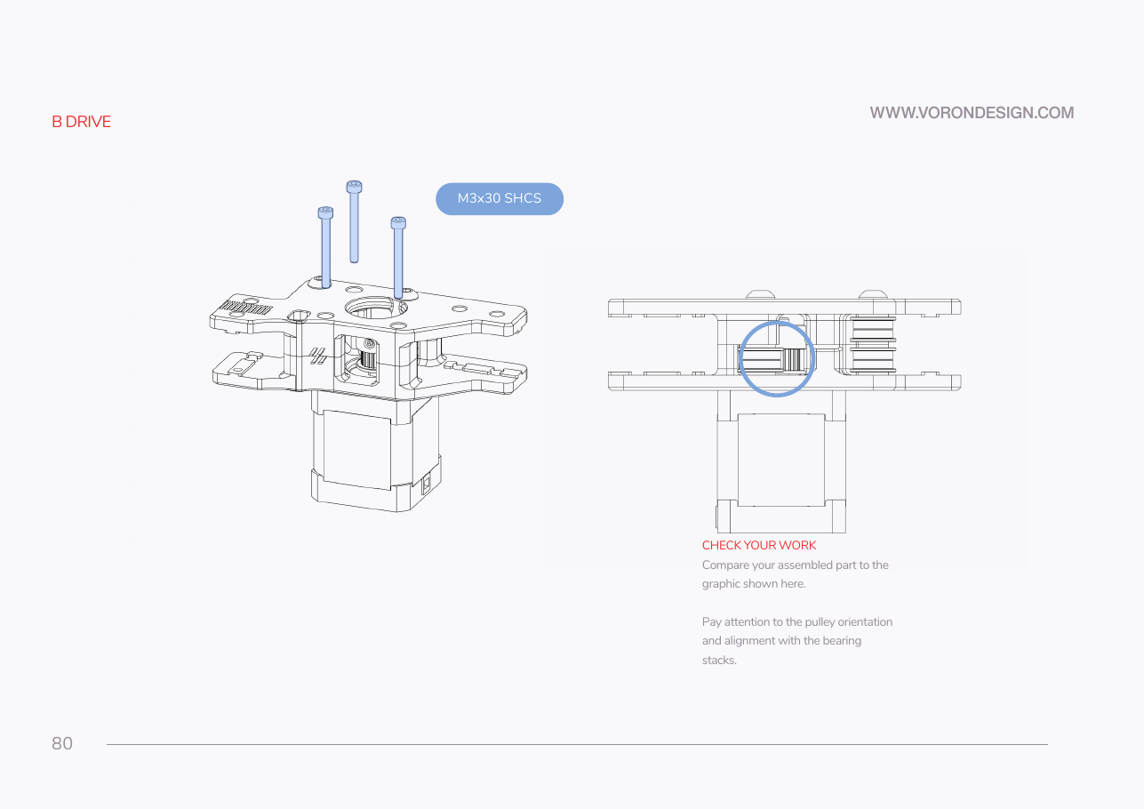 Step 04.36B drive: three M3×30 SHCS through the frames into the motor
Step 04.37B drive: check your work and the belt pathwith a helper

Gather per session — what to lay out before each bench segment.
- Steps 04.1–04.5 · ~30 min — Fasteners, Tools & Misc box: M3×5×4 brass heat-set insert ×4; M5 hex nut ×2 · Printed parts:
a_drive_frame_upper×1 (bin 04-A);[a]_tensioner_right×1 (bin 04-A);[a]_tensioner_left×1 (bin 04-B) · Tools and consumables: four trays or bags; masking tape; marker; caliper; soldering iron with the M3 insert tip; small flat screwdriver · Set out for later steps: the ten printed drive and idler parts; F695 bearing ×16; M5 precision spacer ×16 · Already on the bench: both tension arms - Steps 04.6–04.12 · ~40 min — Motion box: F695 bearing ×2 · Fasteners, Tools & Misc box: M5×40 SHCS ×1; M5 precision spacer ×2; M3 washer ×1; M3×40 SHCS ×1 · Printed parts:
front_idler_right_lower×1 (bin 04-A);front_idler_right_upper×1 (bin 04-A) · Already on the bench:[a]_tensioner_right, insert and M5 nut fitted (bin 04-A); the same M5×40 SHCS - Steps 04.13–04.19 · ~35 min — Motion box: F695 bearing ×2 · Fasteners, Tools & Misc box: M5×40 SHCS ×1; M5 precision spacer ×2; M3 washer ×1; M3×40 SHCS ×1 · Printed parts:
front_idler_left_lower×1 (bin 04-B);front_idler_left_upper×1 (bin 04-B) · Already on the bench:[a]_tensioner_left, insert and M5 nut fitted (bin 04-B); the same M5×40 SHCS - Steps 04.20–04.23 · ~25 min — Motion box: F695 bearing ×6 · Fasteners, Tools & Misc box: M5×30 BHCS ×2; M5 precision spacer ×6 · Printed parts:
a_drive_frame_lower×1 (bin 04-A) · Already on the bench:a_drive_frame_upper, inserts fitted (bin 04-A) - Steps 04.24–04.28 · ~25 min — Motion box: GT2 20 T 6 mm pulley ×1 · Fasteners, Tools & Misc box: M3×30 SHCS ×3 · Motor Kit box: stepper motor, 0.9° A/B ×1 · Tools and consumables: printed
pulley_jig.stl(bin 00-jigs); caliper; Loctite 243; 1.5 mm hex key; free end of the 6 mm belt reel, uncut; masking tape; marker · Already on the bench: the pulley's two set screws; the A motor with its pulley - Steps 04.29–04.37 · ~45 min — Motion box: F695 bearing ×6; GT2 20 T 6 mm pulley ×1 · Fasteners, Tools & Misc box: M5×30 BHCS ×2; M5 precision spacer ×6; M3×30 SHCS ×3 · Motor Kit box: stepper motor, 0.9° A/B ×1 · Printed parts:
b_drive_frame_upper×1 (bin 04-B);b_drive_frame_lower×1 (bin 04-B) · Tools and consumables: printedpulley_jig.stl(bin 00-jigs); caliper; Loctite 243; 1.5 mm hex key; free end of the 6 mm belt reel, uncut; masking tape; marker · Already on the bench: the pulley's two set screws; the B motor with its pulley - Step 04.38 · ~15 min — Tools and consumables: four bags; marker · Already on the bench: the four finished assemblies