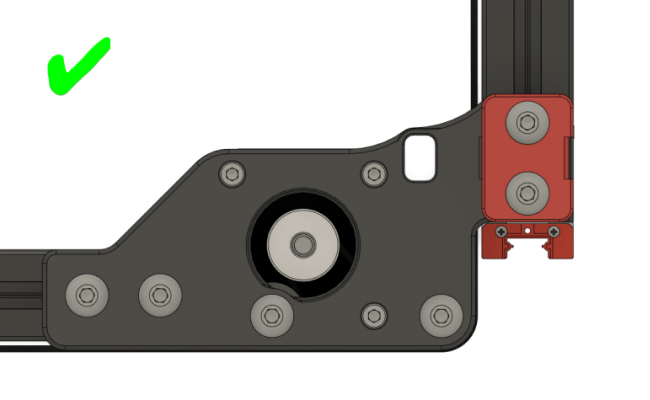
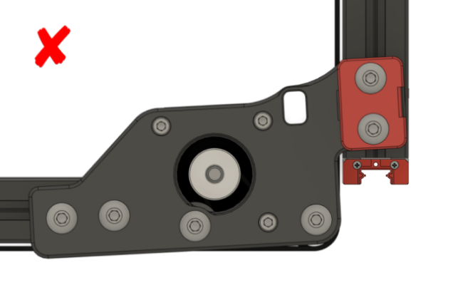
Step 06b.11 — Level the gantry onto the Z joints¶
Step 37 of 42 with a helper · Chapter 06 — Z axis (and Chapter 06b — Gantry squaring)
Parts: none.
Do:
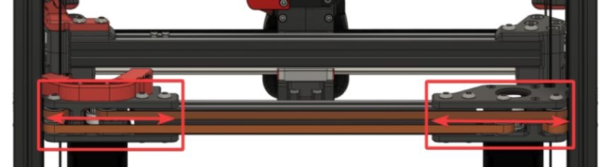
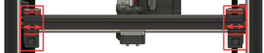
- Slide the six loosened assemblies until the gantry sits on the four lower Z joints.
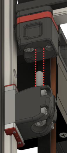
- At each corner raise the lower joint and start the M5×40 by hand: it drops in without coaxing.
 Check
Both Voron conditions met at all four corners, no A/B joint rotated, and the four-point gap measurement inside tolerance.
 Helper Writes the four gap readings into the table as you call them out.
What you're looking at
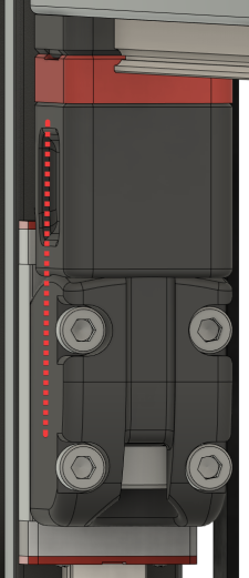
Slide the six loosened assemblies along their extrusions until the gantry's four corners land over the four lower Z joints. Voron's two conditions: the Z joints feel flush along the side, and the M5×40 slides in without hitting the sides.
The four-point gap measurement (bench check, not in the official text)
With the caliper's depth rod, measure the horizontal gap between each Y extrusion and the frame upright beside it, at front-left, rear-left, front-right and rear-right. Front and rear on the same side must agree within 0.5 mm — a difference is the gantry skewed in the frame. Left and right must agree within 1 mm — a difference is the gantry off-centre. Then stand a machinist square on the front frame extrusion at each front corner, blade against the Y extrusion: no light under the blade at either corner. Write the numbers down; you repeat this at 06b.12 and 06b.14.
| Point | Measured (mm) | Pass |
|---|---|---|
| Front-left (left Y ↔ front-left upright) | ||
| Rear-left (left Y ↔ rear-left upright) | ||
| Front-right (right Y ↔ front-right upright) | ||
| Rear-right (right Y ↔ rear-right upright) |
Source: Voron docs § V2 Gantry Squaring, step 9.1–9.2 · images XAdjust.png, YAdjust.png, Alignment-Side.png, Alignment-Hole.png, Alignment-AB-Good.png, Alignment-AB-Bad.png