Chapter 07 — A/B belts and tensioning¶
One page per step
Read this chapter one step per page — big pictures, prev/next, and the same tick marks. This page is the whole chapter in one scroll.
Cut, route and clamp the two CoreXY belts, set a provisional tension, and finish the X carriage with the inductive probe. This makes the gantry a working XY motion system — everything after it (toolhead, wiring, bring-up) assumes the belts are on.
What you're building in this chapter. Two belt loops and the printed carriage that clamps them. In CoreXY neither motor owns an axis: the rear-right motor drives the A belt, the rear-left drives the B belt, and the toolhead moves in X when both turn the same way and in Y when they turn opposite ways. Each belt is one long loop that starts and ends at the X carriage, and on a Voron the two loops sit at different heights and never cross — each stays in its own horizontal plane the whole way round. Where a belt has to be driven it wraps a toothed motor pulley teeth-first; everywhere it is merely turned, it runs smooth-side-on over a plain bearing stack — except at the XY joints, where each belt meets one toothed 20T idler and one plain F695 pair: A rides the left joint's upper plain stack and the right joint's upper toothed idler; B rides the left joint's lower toothed idler and the right joint's lower plain stack (p.105, p.135, p.136, p.138). Whether a face is teeth-on is fixed by which joint and which height — never twist a belt to change it. The A belt is the upper of the two planes, B the lower. Both belts start in the left carriage half and leave it heading left, so A's first turn is on the left joint's plain stack and B's first turn is on the left joint's toothed idler. Both loops are the same length by design, so two belts cut identical arrive at identical tension — and no amount of tensioner adjustment can undo a length error, which is why they are cut against each other and their protruding tails compared at the carriage. The chapter finishes by fitting the inductive probe that later levels the gantry and maps the bed.
Time: 2.5–4.0 h hands-on, first build (survey §5.1 P07 / §7.2 Ch 07).
Sessions: 5 × ~30 min (first-build estimate; each Pause: line carries its own segment minutes — note that segment 3, threading both belts, cannot be broken and needs ~80 min in one sitting — there is a soft stop after Step 07.16 if you must).
Prerequisites:
- Ch 04 (A/B drives and front idlers assembled, motor pulley set screws threadlocked), Ch 05 (gantry, XY joints, X carriage on the rail, Ti backers), Ch 06 Part A (gantry installed on the Z joints, Z belts clamped).
- Print batches B02 (accent:
[a]_tensioner_left/right,[a]_cable_cover), B03 (front idlers), B04 (XY joints + X carriage +probe_retainer_bracket). - The gantry must move freely by hand over its full travel with no belts on. Fix binding now, not after belting.
Tools
- Ball-end hex 2.5 mm, for every screw in this chapter
- Needle-nose pliers and tweezers (belt threading; the manual calls these out on p.132)
- Flush cutters or sharp scissors for belt; steel rule or tape ≥ 2.2 m; 150 mm steel rule for the tension span; marker
- Phone with a spectrum app: Spectroid (Android), Sound Spectrum Analysis (iOS), or Gates Carbon Drive (both — use the "motorcycle" option) (Voron tuning docs)
- Temperature-controlled soldering iron + M3 brass tip, only if the heat-set inserts on p.129 were not done in the Ch 00 insert pass
Printed parts
Parts arrive in the bins named below (see the bin map in print/README.md#bins); check the bin label's list before you start.
| Looks like | STL | Bin | Qty | Colour |
|---|---|---|---|---|
Gantry/X_Axis/X_Carriage/x_frame_V2TR_MGN12_left |
07-X | 1 | Black | |
Gantry/X_Axis/X_Carriage/x_frame_V2TR_MGN12_right |
07-X | 1 | Black | |
Gantry/X_Axis/X_Carriage/probe_retainer_bracket |
07-X | 1 | Black | |
Gantry/Front_Idlers/[a]_tensioner_left |
04-B | 1 | Blue — fitted in Ch 04, adjusted here | |
Gantry/Front_Idlers/[a]_tensioner_right |
04-A | 1 | Blue — fitted in Ch 04, adjusted here | |
Gantry/AB_Drive_Units/[a]_cable_cover |
07-X | 1 | Blue |
Hardware (chapter totals)
| Fastener / part | Qty | Where |
|---|---|---|
| Gates 2GT open belt, 6 mm wide | 2 lengths, cut equal | A and B belts (p.125, p.131 — see Step 07.8) |
| M3×8 SHCS | 4 | belt clamps, 2 per X carriage half (p.131, p.140) |
| M3×12 SHCS | 2 | 1 per X carriage half, in the plain hole beside the belt slot, head 3 mm off the plastic (p.130) |
| M3×30 SHCS | 4 | 2 carriage bolts (p.140) + 2 probe retainer bracket (p.143) |
| M3 nut | 2 | right X carriage half, capture the M3×30 carriage bolts (p.129) |
| M3 heat-set insert | 4 | 1 per X carriage half, in the bottom hole + 2 in probe_retainer_bracket (p.129); the M3×12 stop screws do not use them |
| Inductive probe, Omron TL-Q5MC | 1 | X carriage (p.143) |
| Fibreglass tape (LDO-supplied) | as needed | probe insulation, front + sides only (LDO note p.143) |
Read first
- The tension you set here is provisional. Gantry squaring (Ch 06b) begins by fully releasing A/B belt tension, and it needs a running printer (
G28,QUAD_GANTRY_LEVEL,SET_STEPPER_ENABLE), so it happens inside Ch 13. Set enough tension to home and QGL. A/B tension is set three times on purpose: Ch 07 (provisional — enough to home and QGL), Ch 06b Step 06b.15 (provisional again, after squaring, cold and open) and Ch 14 Step 14.4 (final — panels on, cold, door open, immediately before the closed-chamber soak and hot Z-joint tighten of 14.6). Z belts: 06b.3 (so QGL converges for squaring), set for the last time at 14.5, same cold session. Ch 14 owns the final number; tensioning to final now just gets undone — that is survey §5.2 W1, a ~1.5 h rework. - Equal length is the whole trick. Both belt paths are the same length by design, so if the two belts are cut identical, equal tension follows (p.125). Cut each belt against the other, never to a tape measure alone: fold-cut both at once (Step 07.8), or do as p.125 recommends: route one, remove it, and cut the second to match it.
- There is no sourced deflection number. The official manual gives no tension figure at all — only the equal-length rule. The one sourced number in this build's document set is 110 Hz over a 150 mm span (Voron secondary tuning). voronldo.com's 80–100 Hz is discarded (survey §4.3). Do not substitute a "push it 2 mm with your finger" test — nothing here calibrates it.
- Nothing in this chapter is torqued. Belt clamps and carriage bolts go on lightly, the belts get pulled tight by hand, then the carriage bolts are fully tightened (p.140–141). The manual specifies no torque values; don't invent one.
- Three LDO deviations land in this page range: the X-carriage variant check (p.129–130), probe insulation (p.143), and p.145 skipped entirely.
- The inductive probe is built once, here. Insulation, fitting, the 6 mm height and the cable route are Steps 07.34–07.37 (manual p.143–144). The tape goes on here and nowhere else: Ch 10 Step 10.30 only confirms it. The lead is never cut: it arrives pre-terminated for the toolhead board, and Ch 08 Step 08.50 plugs it in. Ch 08 otherwise only confirms the decision and bags the Klicky set. The
probe_retainer_bracketand the fibreglass tape are counted in this chapter's totals, not Ch 08's.
Sources for this chapter:
- Voron 2.4r2 assembly manual, p.124–145 — the page sequence this chapter transcribes, pinned at commit
de7e89d - Voron docs § Secondary printer tuning — A/B Belts — the only sourced tension figure, 110 Hz over 150 mm, and the source of the spectrum image (GPL-3.0)
- Voron docs § V2 Gantry Squaring — why this tension is provisional
- LDO Build Notes § Voron 2.4 build FAQ — X-carriage variant check, probe insulation, p.145 skipped
- LDO 350 Rev D BOM and onetwo3D's 350 BOM — belt supplied as 6.21 m bulk, 2000 mm per belt
STLs/Gantry/AB_Drive_Units/— the[a]_cable_coverthe manual has no page for
Video coverage (Steve Builds, pre-release LDO kit — differs from Rev D+): Part 4 @1:38:20 (+6m), Part 5 @1:52:44 (+8m), Part 6 @0:01:10 (+18m), Part 8 @1:43:45 (+6m)
Understand the path before you cut anything¶
Step 07.1 — Confirm the gate before you start¶
What you're looking at: The gate check. You have a gantry that slides freely in X and Y with nothing driving it. The two CoreXY belts are the last mechanical link, and they thread through six separate bearing stacks. Binding is far cheaper to find now.
Parts: none.
Do:
- Confirm the gantry is on the Z joints and the Z belts are clamped, from Ch 06 Part A.
- Push the gantry through its full Y travel and the X carriage through its full X travel by hand.
 Check
No notchiness, no rising resistance at either end of travel, no carriage running off a rail. The X carriage coasts when pushed.
Source: Voron manual p.124
Step 07.2 — Learn the rule that governs this chapter¶
What you're looking at: The concept page. In CoreXY neither motor owns an axis: two belt loops connect both motors to the carriage. The toolhead moves in X when the motors turn together, in Y when they turn opposite ways. Both paths are the same length by design.
Parts: none.
Do: Read p.125. The two belt paths are stacked at different heights and never cross: each belt stays in one horizontal plane for its entire loop. Equal length is how you get equal tension.
Check
You can state, without looking, where the A belt leaves the carriage and where it comes back.
Source: Voron manual p.125
Step 07.3 — Trace the A belt path¶
What you're looking at: The A belt is the one driven by the rear-right motor, and it is the upper of the two belt planes: its motor pulley and front idler sit 10 mm higher than B's. The diagram traces the same loop top-down.
Parts: none.
Do: Trace on p.126: X carriage → left XY joint → left Y rearward → rear-left idler stack → rear extrusion → A drive S-wrap → right Y forward → front-right idler U-turn → rearward → right XY joint → carriage.
Check
On the right-hand side the A belt gives two parallel runs, on the left one. The A drive is the rear-right unit. survey
Source: Voron manual p.126
Step 07.4 — Trace the B belt path¶
What you're looking at: The B belt is A's mirror image, driven by the rear-left motor in the lower plane: two runs on the left, one on the right. Each drive unit carries a toothed motor pulley for its own belt and a plain stack for the other.
Parts: none.
Do: Trace on p.127: X carriage → left XY joint teeth-on → left Y forward → front-left idler U-turn → B drive S-wrap → rear extrusion → rear-right idler stack → right Y forward → right XY joint smooth → carriage.
Check
You can say which XY joint B turns first, the left, and which face it shows there, teeth. Never wrap both belts on one pulley.
Source: Voron manual p.127
Prepare the idlers and the X carriage¶
Step 07.5 — Set both front-idler tensioners¶
What you're looking at: The front-idler tensioners are the two blue parts at the front; each carries an M3×40 whose job is belt tension. Winding it in pulls the idler forward and tightens that belt, backing it out releases it. Both went on in Ch 04.
Parts:
- reused: the two front-idler M3×40 SHCS
- reused: the two front-idler M3 washers
Do:
- Back each M3×40 out until the tension arm is at its slackest end of travel.
- Wind it back in exactly 4 turns. Count the turns and give both idlers the same number.
Check
Both tensioner screws stand proud of the front idler bodies by the same amount, with travel left in both directions.
Helper: Counts the four turns aloud on each tensioner so both idlers get the same number.
Source: Voron manual p.128 · Voron docs § V2 Gantry Squaring, step 5
 Good stopping point · ~25 min since the last one
both belt paths traced against p.126–127 and both front-idler tensioners backed out to the loose starting position. Nothing is cut. Do not start cutting belt unless you can also thread it.
Step 07.6 — Fit the heat-set inserts and M3 nuts¶
What you're looking at: A heat-set insert is a knurled brass sleeve melted into the plastic so a steel screw has metal threads to bite into. Four go in here: one per X carriage half, two in the probe retainer bracket. The halves are a handed pair.
Parts:
x_frame_V2TR_MGN12_left×1x_frame_V2TR_MGN12_right×1probe_retainer_bracket×1- M3 heat-set insert ×4
- M3 nut ×2
Do:
- If the inserts went in during the Ch 00 pass, verify them. Otherwise set all four flush with the plastic, square to the face.
- Press the two M3 nuts into their pockets in the right carriage half.
Check
Inserts flush and square; nuts fully seated with no gap behind them; an M3 screw starts by hand in every insert.
Caution
Rev D+ / LDO: "If you are building Clockwork 2 double-check that you have the correct X-Carriage and follow the instructions in the Stealthburner manual." For this kit that is the pair x_frame_V2TR_MGN12_left / x_frame_V2TR_MGN12_right — the R2 / Clockwork-2 halves, not the Afterburner ones. Confirm the filenames against what you actually printed before the belts go in. src (p.129–130)
Source: Voron manual p.129 · LDO Build Notes § Voron 2.4 build FAQ
Step 07.7 — Set the two carriage stop screws to 3 mm¶
What you're looking at: These two M3×12 are stop screws rather than fasteners. The 3 mm of thread standing proud of each half sets how the two halves meet over the belt, so the two must match each other as well as the number.
Parts:
- M3×12 SHCS ×2
Do: In each carriage half, thread one M3×12 into the plain hole beside the belt slot on p.130, not the heat-set insert at the bottom. Stop when the head stands 3 mm off the plastic. Measure with the caliper depth blade.
Check
Both screws at 3 mm ±0.5 mm, and the same on both halves.
Source: Voron manual p.130
Cut and clamp¶
Step 07.8 — Cut both belts to the same length¶
(no image — see text)
What you're looking at: No picture, and the most consequential measurement in the chapter. Both belt paths are the same length by design, so two belts of identical length arrive at identical tension. A few millimetres of difference is a permanent imbalance the tensioners cannot remove.
Parts:
- consumable: Gates 2GT open belt, 6 mm wide, two equal lengths
Do:
- Measure 2000 mm from the free end and fold the belt back there.
- Lay the doubled belt flat and cut through both layers at the fold, square across.
- Cut the reel side level with the free end.
Check
Both belts side by side against a square edge: the far ends flush. About 100 mm of tail reaches each clamp (verify on bench).
Tip
Mark one belt A with a dot on the smooth back near each end: it goes into the upper slot. Once both are threaded they are impossible to tell apart.
Tip
Voron's own method, p.125: route the first belt off the reel as A, mark its length, remove it, cut it, then cut the second against it.
Source: Voron manual p.125 · LDO 350 Rev D BOM · LDO Build Notes § Voron 2.4 build FAQ · onetwo3D Voron 2.4 350 BOM
Good stopping point · ~30 min since the last one
heat-set inserts and M3 nuts in the carriage halves, stop screws set to 3 mm, both belts cut to matched length and marked A and B. Coil the two belts and bag them; the next segment is the one that cannot be broken.
Step 07.9 — Clamp the first end of both belts in the left carriage half¶
What you're looking at: The X carriage clamps a belt by squeezing it between its two printed halves. Both belts' first ends go into the left half, one upper, one lower. The upper slot is A, whose pulley and idler sit 10 mm higher than B's.
Parts:
- reused: the left X carriage half
- reused: both cut belts, marked A and B
- M3×8 SHCS ×2
Do:
- Feed belt A into the upper slot of the left carriage part, B into the lower, teeth away from the extrusion.
- Hold the left part, belts in, against the rail carriage; run both M3×8 SHCS in, snug only.
Check
Both ends captured and immovable under a firm tug, the A mark in the upper slot, teeth facing the same way, neither belt twisted.
Source: Voron manual p.131
Route the A belt¶
Work in one direction round the loop. Needle-nose pliers or tweezers make the bearing stacks manageable (p.132). Do not force a belt round a stack — if it will not go at a front idler, use the access trick in Step 07.15.
Step 07.10 — A belt: leave the carriage and turn at the left XY joint¶
What you're looking at: The left XY joint's upper, plain F695 pair is where the A belt turns 90°, smooth back on the bearings. The toothed idler below it belongs to B. Centred in the groove is the whole requirement: a belt climbing a flange frays.
Parts:
- reused: the A belt
Do: Take the A belt end left along the X extrusion to the left XY joint. Wrap it 90° around the joint's plain bearing stack, smooth back on the bearings, so it runs rearward along the left Y extrusion.
Check
The belt sits centred in the stack groove, not climbing a flange, smooth back on the bearings, with no twist back to the carriage.
Source: Voron manual p.132
Step 07.11 — A belt: run rearward up the left Y extrusion¶
What you're looking at: The single long run down the left-hand side of the machine. Nothing turns the belt here, so the only things to get right are that it stays parallel to the extrusion and clears every printed part on the way.
Parts:
- reused: the A belt
Do: Run the belt straight back along the left Y extrusion to the rear-left drive unit. This is the single run on the left side of the machine, the p.126 top-left inset.
Check
The run is parallel to the extrusion along its whole length and clears the printed parts and the Z belt.
Source: Voron manual p.126
Step 07.12 — A belt: turn 90° at the rear-left idler stack¶
What you're looking at: The rear-left corner is the B drive unit, carrying two things at two heights: B's toothed motor pulley, and a plain bearing stack that belongs to the A belt. A wraps the plain stack only. Wrapping the pulley instead would lock the axes together.
Parts:
- reused: the A belt
Do: Wrap the belt round the idler stack at the rear-left corner, smooth back on it, not the B motor pulley beside it. Turn it to run right along the rear extrusion towards the A drive.
Check
The B motor pulley is untouched and free to spin. The A belt runs along the rear extrusion at a constant height.
Source: Voron manual p.126
Step 07.13 — A belt: S-wrap the A drive motor pulley¶
What you're looking at: The S-wrap gives a drive pulley its grip: the belt comes in over one bearing, wraps a large arc of the toothed motor pulley, and leaves over a second bearing. More teeth in contact means the belt cannot skip under hard acceleration.
Parts:
- reused: the A belt
Do: At the rear-right A drive unit, take the belt round the first stack, over the toothed motor pulley, and back out round the second, the S-shape on p.133. Seat the belt on the pulley teeth, not on a flange.
Check
Nudge the belt: the motor pulley indexes tooth by tooth and does not slip. The belt leaves heading forward along the right Y extrusion.
Source: Voron manual p.133
Step 07.14 — A belt: run forward down the right Y extrusion¶
What you're looking at: The outbound A run passes the right XY joint at its own height without wrapping it; that joint comes on the return run. Sighting the belt at the same height at both ends of a long run catches a half-twist.
Parts:
- reused: the A belt
Do: Run the belt forward along the right Y extrusion, past the right XY joint without wrapping it, all the way to the front-right idler. The left-hand image on p.134 shows the belt passing the joint at its own height.
Check
The belt clears the XY joint's printed parts entirely, no rub, no contact, and is at the same height at both ends of the run.
Source: Voron manual p.134
Step 07.15 — A belt: U-turn at the front-right idler¶
What you're looking at: The front-right idler is a 180° turnaround: the belt goes round it and comes straight back, which is why the right-hand side ends up with two parallel runs. It is the smooth back of the belt that rides this stack, not the teeth.
Parts:
- reused: the A belt
Do: Wrap the belt 180° around the front-right idler bearing stack and bring it back rearward, parallel to the run you just made.
Check
Two right-side runs, parallel and not touching. Smooth back on the idler, teeth away from it on both runs: outboard outbound, inboard returning.
 Tip
If the stack will not take the belt, remove that idler's M3×40 SHCS tensioner screw, thread the belt, refit, then redo Step 07.5. No drive or joint has that screw.
Source: Voron manual p.134
Step 07.16 — A belt: turn at the right XY joint and return to the carriage¶
What you're looking at: The right XY joint closes the A loop. The belt wraps the joint's upper, toothed 20T idler teeth-on: the return run doubled back at the front idler, so its teeth now face inboard. This is correct, not a mis-route.
Parts:
- reused: the A belt
Do: Take the returning run rearward to the right XY joint. Wrap it 90° round the joint's toothed idler, teeth meshing, then bring it left along the X extrusion to the X carriage. Leave the tail loose there.
Check
A is now a closed path, both ends at the carriage, teeth on the right joint's toothed idler and smooth back everywhere else.
Soft stop (not a Pause): if you must break here, tape the loose A tail to the X beam so it cannot pull back through a stack. On resuming, walk the six A wraps with a fingertip before starting Step 07.17.
Source: Voron manual p.135
Route the B belt¶
B goes in one plane below A and the other way round the frame: both belts leave the left carriage half heading left, so B's first turn is the left XY joint — the one A merely passed on its way back — and its last is the right joint. The manual's B pages (p.136 → p.137 → p.138) run in exactly this order.
Step 07.17 — B belt: leave the carriage and turn teeth-on at the left XY joint¶
What you're looking at: The left XY joint, one plane down. Below the plain F695 pair that A already wraps sits the joint's toothed 20T idler: B's first turn is on it, teeth meshing, turning the belt from X to forward down the left Y extrusion.
Parts:
- reused: the B belt
Do:
- Take the B belt end left along the X extrusion, below A, to the left XY joint.
- Wrap it 90° round the joint's lower, toothed idler, teeth meshing, so it runs forward along the left Y extrusion.
Check
B's teeth centred on the toothed idler, A on the plain stack directly above with a visible gap, and B leaves heading forward, no twist.
Source: Voron manual p.136 · Voron manual p.105
Step 07.18 — B belt: run forward and U-turn at the front-left idler¶
What you're looking at: The 180° turnaround at the front-left idler, which gives the left-hand side its two parallel runs. The mirror of A's front-right turn: the smooth back rides the stack and the teeth face away from it. For B it comes early in the loop.
Parts:
- reused: the B belt
Do: Run the belt forward along the left Y extrusion to the front-left idler. Wrap it 180° round the idler bearing stack, smooth back on it, and bring it rearward on the outer run, parallel to the run you just made.
Check
Two parallel, non-touching runs on the left side. Smooth back on the idler, teeth away from it on both runs: inboard outbound, outboard returning.
Tip
If the stack will not take the belt, remove that idler's M3×40 SHCS tensioner screw, thread the belt, refit, then redo Step 07.5. No drive or joint has that screw.
Source: Voron manual p.136
Step 07.19 — B belt: run rearward up the left outer run, past the left XY joint¶
What you're looking at: B's return run up the left side, outboard of the forward run. It passes the left XY joint at its own height without touching it, on to the B drive at the rear-left. Sight both ends at the same height to catch a half-twist.
Parts:
- reused: the B belt
Do: Run the belt rearward along the left Y extrusion on the outer run, past the left XY joint without wrapping anything, all the way to the rear-left B drive unit.
Check
The belt clears the joint's printed parts and the inner run, both left-side runs stay parallel, and the height is the same at both ends.
Source: Voron manual p.137
Step 07.20 — B belt: S-wrap the B drive motor pulley¶
What you're looking at: The same S-wrap as the A drive, this time on the B motor at the rear-left: bearing stack, toothed motor pulley, bearing stack. The plain stack on this unit that A already turns on sits at another height and is not touched.
Parts:
- reused: the B belt
Do: At the rear-left B drive unit, take the belt round the first stack, over the toothed motor pulley, and back out round the second, the S-shape on p.137. Seat it on the pulley teeth, not a flange.
Check
Nudge the belt: the B pulley indexes tooth by tooth, no slip. A is untouched on its idler stack. B runs below A.
Source: Voron manual p.137
Step 07.21 — B belt: run right along the rear and turn 90° at the rear-right idler stack¶
What you're looking at: The rear-right corner is the A drive unit and, like the rear-left, carries a motor pulley and a plain stack. B wraps the plain stack only, smooth back on it, and turns from the rear extrusion to forward down the right Y.
Parts:
- reused: the B belt
Do: Run the belt right along the rear extrusion to the A drive unit. Wrap it 90° round that unit's idler stack, not the A motor pulley beside it, and turn it forward down the right Y extrusion.
Check
The A motor pulley still turns freely. B runs along the rear below A, not touching it, and leaves forward as the single right-side run.
Source: Voron manual p.138
Step 07.22 — B belt: run forward, turn smooth at the right XY joint and return to the carriage¶
What you're looking at: The right XY joint closes the B loop. Here the belt meets the joint's lower, plain F695 stack, smooth back on the bearings, with A's toothed idler directly above it. The mirror of the left joint, one plane down.
Parts:
- reused: the B belt
Do:
- Run the belt forward along the right Y to the right XY joint.
- Wrap it 90° round the joint's lower, plain stack, smooth back and under A's toothed idler, then left to the carriage. Leave the tail loose.
Check
B's smooth back on the lower plain stack, A on the toothed idler above with a visible gap. Both belts are now closed paths.
Source: Voron manual p.138
Step 07.23 — Check both belts against the overviews before closing the carriage¶
What you're looking at: Two complete loops, still open at the carriage: the last moment when a mis-route costs minutes rather than an hour. Four things get tested: teeth on the toothed wheels, smooth back on every plain stack, no half-twist, belts stacked not crossed.
Parts: none.
Do:
- Put p.126 and p.127 beside the machine and walk both loops.
- Nudge the belt at each motor pulley and watch it index rather than slip.
- Sight down every straight run: teeth the same way at both ends.
Check
Teeth on both motor pulleys and the two toothed XY-joint idlers, smooth back on every plain stack, no half-twist, belts stacked not crossed, pulleys free.
Helper: Reads out each stop on the loop from p.126 and p.127 while you check it on the machine.
Source: Voron manual p.127 · Voron manual p.126
Capture the ends, pull tight, inspect¶
Step 07.24 — Fit the right X carriage half to capture the belt ends¶
What you're looking at: The right carriage half is the other jaw of the clamp. Each loose tail goes into the slot at its own height, so the two belts stay in their own planes right up to the point where they are gripped.
Parts:
- reused: the right X carriage half
- reused: both belts, tails loose
Do: Feed the two loose belt tails into their clamp slots in the right X carriage part, each into the slot at its own height, and offer the part up to the carriage. Don't fasten anything yet.
Check
Both tails are seated in their slots and both belts leave the carriage without twist.
Source: Voron manual p.139
Step 07.25 — Fix the belts, lightly¶
What you're looking at: Deliberately loose. The clamp still has to let belt be pulled through, because the next steps take the slack out of both loops by pulling on these tails. Tighten now and you lock the slack in.
Parts:
- M3×8 SHCS ×2
Do: Run the two M3×8 SHCS into the right carriage half. "Lightly tighten the screws. The belt must still be able to move." You must still be able to pull belt through the clamp.
Check
You can still draw belt through the clamp by hand with moderate effort.
Source: Voron manual p.140
Step 07.26 — Fit the carriage bolts and leave them loose¶
What you're looking at: The two M3×30 pass through both carriage halves into the M3 nuts you pressed in earlier; they are what squeeze the halves together onto the belts. Left light too, for the same reason as the clamp screws.
Parts:
- M3×30 SHCS ×2
Do: Pass the two M3×30 SHCS through the carriage, one top, one bottom, into the captive M3 nuts. "Lightly tighten the bolts."
Check
The two carriage halves are held together but can still shift slightly. Nothing is torqued.
Source: Voron manual p.140
Step 07.27 — Pull both belts tight and equalise the tails¶
What you're looking at: This is where belt tension is really set; the tensioners only trim it. Because both belts and both paths are the same length, equal tail length protruding from the carriage is a direct measurement of equal tension.
Parts: none.
Do:
- Grab both belt ends with pliers and pull the belt tight, until the same length protrudes from the carriage on both belts.
- Pull one, then the other, then back again; they interact. Tuck the excess into the carriage.
Check
Tails match on the rule, and still match after moving the gantry through full XY travel. If one crept, back off its M3×8 and re-pull.
Helper: Reads both tail lengths off the rule and says which belt sticks out further.
Source: Voron manual p.141 · Voron docs § Secondary printer tuning — A/B Belts
Step 07.28 — Tighten the carriage bolts¶
What you're looking at: Everything closed and firm at last. These screws go into printed plastic and captive nuts, so "solid" is the stopping point: the manual gives no torque figure, and a stripped insert here means splitting the carriage back open with both belts threaded through it.
Parts: none.
Do: Fully tighten the four M3×8 belt-clamp screws first, as p.141's middle panel shows. Then "Fully tighten the carriage bolts." These thread into plastic and captive nuts, so stop at solid (not specified — snug).
Check
Pull hard on each belt at the carriage: nothing slips. The X carriage still runs the full X rail without fouling.
Source: Voron manual p.141
Good stopping point · ~80 min since the last one
the long one, and it has no safe interior stop: both belts routed, both ends captured in the carriage, tails equalised and the carriage bolts tightened. Only stop here once the carriage is closed and both belts are held at both ends.
Step 07.29 — Belt-rub inspection at every idler stack¶
What you're looking at: Fourteen belt contacts at six locations: two per XY joint, one per front idler, and four per drive: two S-wrap stacks, the motor pulley and the other belt's stack. A belt riding a printed flange ticks once per revolution.
Parts: none.
Do:
- "Make sure that the belt is not riding on the plastic parts." Look at both belt edges entering and leaving every stack.
- Repeat with the gantry at the extreme front, the extreme rear, and both ends of X.
Check
Visible daylight between both belt edges and the printed part at every stack in every position. No witness marks, dust, tick or squeak.
Helper: Watches one side of every stack as you move the gantry and calls out any rub.
Source: Voron manual p.142 · Voron docs § V2 Gantry Squaring, step 5 · Video: Part 4 @1:39:56
Initial tension (provisional)¶
Provisional: the squaring procedure starts by releasing this tension completely (V2 gantry squaring, step 5; survey §4.4 #2 and §5.2 W1). What you set here only needs to be good enough to home, QGL and run the bring-up in Ch 13; Ch 14 Step 14.4 owns the final number.
Step 07.30 — Set the 150 mm measuring span¶
What you're looking at: The two idlers a belt runs between, one in the XY joint, one in the front idler block, and the free belt between them that you pluck. A plucked belt's pitch depends on the span, so the figure means nothing without it.
Parts: none.
Do: Move the X extrusion forwards by hand until the XY joint idler centres are 150 mm from the front idler centres. Measure centre to centre with the rule on both sides, with the gantry square to the frame, not skewed.
Check
150 mm on the left and 150 mm on the right, measured to the same features.
Helper: Holds the rule between the two idler centres and reads the number aloud on each side.
Tip
The CAD shows a parked 250 machine, not the measuring pose. Take which two centres from the picture, take the number from the rule.
Source: Voron docs § Secondary printer tuning — A/B Belts · Voron manual p.141 · Video: Part 6 @0:10:08 · CAD: Voron 2.4r2 STEP @ de7e89d
Step 07.31 — Read both belts with the phone¶
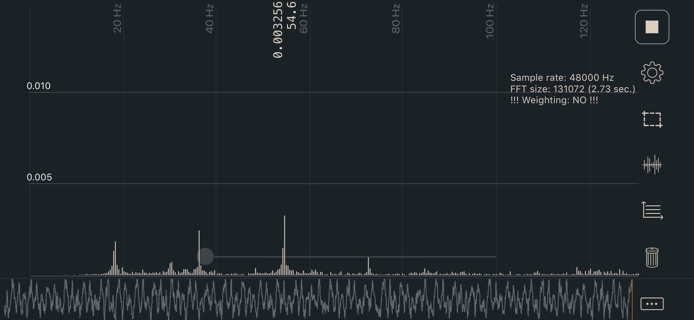
What you're looking at: The spectrum app turns a plucked belt into a plot of frequency against level. The number you want is the lowest peak, the fundamental. A belt also rings at two and three times that, and a harmonic reads as twice the real tension.
Parts: none.
Do:
- Start the spectrum app, hold the phone close to the belt, and pluck the free 150 mm section like a guitar string.
- Read the lowest frequency peak, not the loudest and not a harmonic. Do both belts.
Check
Three plucks in a row land within a few Hz of each other. A reading that jumps around is a harmonic or room noise.
Helper: Holds the phone by the belt and reads the lowest peak aloud after each pluck.
Source: Voron docs § Secondary printer tuning — A/B Belts · image sound-spectrum-belt.jpg
Step 07.32 — Bring both belts to ~110 Hz¶
(no image — see text)
What you're looking at: The two tensions interact: tightening one belt shifts the X extrusion and changes the other. That is why this converges by alternating quarter turns between the two rather than by finishing one belt and then starting the other.
Parts: none.
Do:
- Adjust with the front-idler tensioner screws: in for more tension, out for less. Target ~110 Hz over the 150 mm span, about 2 lb.
- The two tensions affect each other, so alternate quarter turns until they are equal.
Check
Both belts read ~110 Hz. Do not chase the number; this tension is provisional and Ch 14 Step 14.4 sets it last.
Helper: Reads each belt's lowest peak aloud after every quarter turn you make.
Source: Voron docs § Secondary printer tuning — A/B Belts
Step 07.33 — Move the gantry, return, and re-check¶
(no image — see text)
What you're looking at: Moving the gantry and bringing it back re-seats both belts in every stack and lets any trapped slack redistribute. A reading that only holds while the gantry has not moved is not a reading.
Parts: none.
Do: Move the X extrusion back at least a few centimetres and then forward again to re-establish the 150 mm span. Re-measure both belts.
Check
Both belts read within a few Hz of each other, at about 110 Hz, after moving the gantry and returning.
Why equality beats the absolute number here — and what to do if they won't converge
Equality between A and B matters more right now than hitting 110 Hz exactly: unequal A/B tension racks the gantry and will fight the squaring you do in Ch 06b, which releases this tension completely anyway. If the two will not converge, the usual causes in order are unequal belt lengths (Step 07.8), unequal tail protrusion at the carriage, or a belt rubbing somewhere.
Source: Voron docs § Secondary printer tuning — A/B Belts · survey §7.2 Ch 07 · Video: Part 6 @0:15:01
Good stopping point · ~30 min since the last one
belt-rub inspection clean at all fourteen contacts, both belts reading ~110 Hz over a 150 mm span and equal to each other after moving the gantry. This tension is provisional; do not chase the number further — Ch 06b releases it entirely and Ch 14 sets it for the last time.
Finish the X carriage: inductive probe¶
Step 07.34 — Insulate the probe and keep its lead whole¶
What you're looking at: The inductive probe is a small rectangular block with two mounting holes at the top and a lead out of it. It senses the steel bed without touching it, for QGL and the bed mesh.
Parts:
- staged: Omron TL-Q5MC inductive probe ×1, in the Toolhead PCB Cables bag
- consumable: fibreglass tape 2×12 cm
Do:
- Wrap at least two layers of fibreglass tape round the front and sides of the block, set slightly up from the bottom edge.
- Leave the lead full length and coil the spare loosely.
Check
Back and bottom sensing face bare; mounting holes clear; lead uncut with its connector on.
Caution
Rev D+ / LDO: p.143's "cut the probe wires to about 150 mm" does not apply. This kit's probe lead comes pre-cut and crimped for the Nitehawk PROBE port, Step 08.50. Tape before fitting; too much tape stops the probe triggering, so peel some off if it fails in Ch 13. src
Source: Voron manual p.143 · LDO Build Notes § Voron 2.4 build FAQ · LDO wiring guide § Insulating the Z probe · LDO 350 Rev D BOM
Step 07.35 — Fit the probe and its retainer bracket¶
What you're looking at: The retainer bracket is the small printed bar with two heat-set inserts that sits behind the carriage. The two M3×30 clamp the probe block to the carriage face through it. Snug only: the probe still slides for the next step.
Parts:
- Omron TL-Q5MC inductive probe ×1
- reused: the probe retainer bracket
- M3×30 SHCS ×2
Do: Hold the probe on the carriage face, lead up. Pass the two M3×30 SHCS through its mounting holes and the carriage into the retainer bracket's inserts behind. Snug enough to hold the probe but still let it slide.
Check
The probe is held square, parallel to the carriage face, and can still be pushed up and down with firm finger pressure.
Source: Voron manual p.143
Step 07.36 — Set the probe height¶
What you're looking at: 6 mm of probe standing below the plastic is a starting position, not a calibration. It puts the sensing face where it will see the bed with margin to spare. The real trigger offset is measured during bring-up in Ch 13.
Parts: none.
Do: Set the probe so its tip sits about 6 mm below the plastic part. This is a starting position only; it gets fine-tuned during bring-up in Ch 13. Then fully tighten the two M3×30.
Check
6 mm ±1 mm, measured with the caliper depth blade. The probe does not move when you push on it.
Helper: Reads the caliper depth aloud while you slide the probe to 6 mm.
Source: Voron manual p.144
Step 07.37 — Route the probe cable¶
What you're looking at: The moulded slot is the one place the probe cable can sit without being caught between the belts and the rail carriage across the full X travel. It plugs into the toolhead board in Ch 08.
Parts: none.
Do: Guide the probe cable into the moulded slot in the carriage. Leave the coiled end loose above the carriage until Step 08.50 plugs it into PROBE.
Check
The cable is captive in the slot and clear of both belts and the rail carriage over full travel. Move the carriage end to end.
Helper: Slides the X carriage slowly end to end while you watch the probe cable.
Source: Voron manual p.144
Step 07.38 — Hall-effect endstop magnet: skip¶
What you're looking at: A page you skip entirely. The pocket shown in the carriage takes a magnet for the hall-effect endstop option; this kit uses a microswitch PCB in the printed endstop pod fitted in Ch 05, so the pocket stays empty.
Parts: none.
Do: Nothing.
Check
No magnet in the carriage pocket.
Caution
Rev D+ / LDO: "PAGE 145 SKIP — The kit does not use hall effect endstops." This kit ships the XY microswitch PCB and the [a]_endstop_pod_D2F_switch printed part (fitted in Ch 05). Do not insert a 3×6 magnet. src (p.145), survey §4.2
Source: Voron manual p.145 · LDO Build Notes § Voron 2.4 build FAQ
Step 07.39 — Fit the A/B drive cable cover¶
What you're looking at: The [a]_cable_cover is the blue shroud that clips over a drive unit's cable exit and tidies the A/B motor leads. The two belts run past it, so it must never touch them. It goes on now while the rear of the gantry is still open.
Parts:
[a]_cable_cover×1
Do: Clip the accent cable cover onto the drive-unit cable exit. If the A/B motor leads are not yet dressed, leave it off and fit it during the gantry cable routing in Ch 10 instead.
Check
The cover does not touch either belt at any point of travel. Re-run the Step 07.29 rub inspection at that drive unit.
Source: STLs/Gantry/AB_Drive_Units/ · Voron manual p.142 · CAD: Voron 2.4r2 STEP @ de7e89d
Checkpoint 07¶
- Both belts routed to match p.126 (A) and p.127 (B); each belt stays in one plane, neither crosses the other.
- No half-twist anywhere; belt teeth face away from the extrusion at the X carriage; each belt's toothed face stays on the same side all the way round.
- Teeth meshed on both toothed motor pulleys — each pulley indexes when the belt is nudged, no slip — and on the two XY-joint toothed idlers (A at the right joint, B at the left); smooth back on every plain stack.
- Belt not riding on any printed part at any of the fourteen contacts at six locations, checked at both ends of X travel and both ends of Y travel (p.142).
- Equal length of belt protruding from the X carriage on both belts, after moving the gantry and returning (p.141).
- Carriage bolts and all four M3×8 belt clamps fully tightened; nothing slips under a hard pull.
- Both belts read within a few Hz of each other at ~110 Hz over a 150 mm span, re-checked after moving the gantry — provisional; Ch 14 Step 14.4 sets the final value.
- Gantry moves through the full XY envelope by hand with even resistance, no ticking, no notchiness.
- Probe insulated (front + sides only), fitted, lead uncut with its factory connector, tip 6 mm below the plastic, cable in its channel.
- No hall-effect magnet fitted (p.145 skipped).
- Turn the A motor pulley by hand: the carriage moves diagonally. Turn both pulleys the same way: it moves in a straight line. That is CoreXY.
Common mistakes¶
- Tensioning to final now. Ch 06b releases A/B tension completely as its first move, and it cannot run until the printer is alive (Ch 13); the final value is Ch 14 Step 14.4 — cold, door open, just before the 14.6 soak. Set ~110 Hz, confirm A ≈ B, move on. Chasing the last 5 Hz here is time you will spend again.
- Cutting the second belt to a tape measure instead of against the first. Any length error becomes a permanent tension imbalance you will try to fix with the tensioners, which cannot fix it. Fold-cut both together, or remove the routed first belt and cut the second against it (Step 07.8).
- Wrapping the wrong element of a rear drive unit. Each drive unit holds the motor pulley for its own belt and an idler stack for the other belt. Putting the A belt on the B motor pulley looks plausible and locks the two axes together. The p.126 top-left and p.127 top-right insets show which is which.
- A half-twist in a long run. It shows up as a belt that runs fine at one end of travel and rubs at the other. Sight down each straight run and confirm the teeth face the same way at both ends.
- "Fixing" the teeth-on turn at an XY joint with a half-twist. Each belt meets one toothed idler at the XY joints — A at the right joint (Step 07.16), B at the left (Step 07.17) — and wraps it teeth-on by design. A twist put in to get the smooth back there walks the belt off a flange at the far end of travel.
- Reading a harmonic on the phone. Spectrum apps show peaks at 2× and 3× the fundamental; 220 Hz reads as "too tight" and sends you loosening a correctly tensioned belt. Take the lowest peak, and take three plucks.
- Forcing a belt round a bearing stack. You will damage the flange or unseat a bearing. At a front idler, pull the M3×40 SHCS, thread the belt, refit and redo Step 07.5 (Step 07.15, p.134). A drive unit or XY joint has no such screw — find what is fouling instead.
Next¶
Ch 08 — Toolhead: Stealthburner, Clockwork 2 and the Nitehawk-SB V2, where all five Rev D+ deviations land.
Good stopping point · ~30 min since the last one
inductive probe insulated, fitted, set to height and its cable routed; endstop magnet correctly skipped; A/B cable cover on. Gantry is a working XY system. Do not tension further and do not square the gantry.