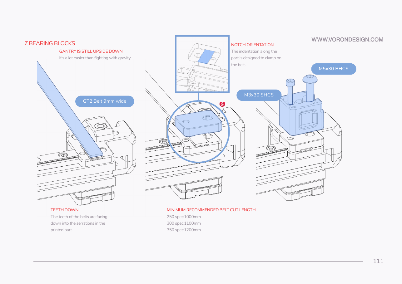
Step 06.5 — Lay the first belt end under the gantry corner
Step 5 of 42 · Chapter 06 — Z axis (and Chapter 06b — Gantry squaring)
Tap to enlarge
 Gather for this segment — steps 06.5–06.8 (~40 min)
Fasteners, Tools & Misc box
- M3×30 SHCS ×4
- M5×30 BHCS ×4
Printed parts
[a]_z_belt_clip_lower_x4×4 · bin 06-Z-joints
Already on the bench
- one cut Z belt
- one Z bearing block with its M5 nut
- the other three cut Z belts
- the other three Z bearing blocks
Parts:
- one cut Z belt · already on the bench
Do:
- Work on the gantry off the printer, upside down, A/B motors up.
- Lay one belt end on a front idler's or drive's serrated pad, teeth down.
- Leave ~10 mm of belt past the pad.
 Check
Belt teeth are meshed into the pad's serrations, not sitting on top of them. The belt leaves the pad straight, not skewed.
What you're looking at
The first belt end goes onto the serrated pad under a gantry corner, a front idler or A/B drive, facing up while the gantry is upside down. Teeth down, the belt meshes into the plastic and cannot creep under load.
Source: Voron manual p.111 · Voron manual p.106 · Video: Part 4 @0:10:12