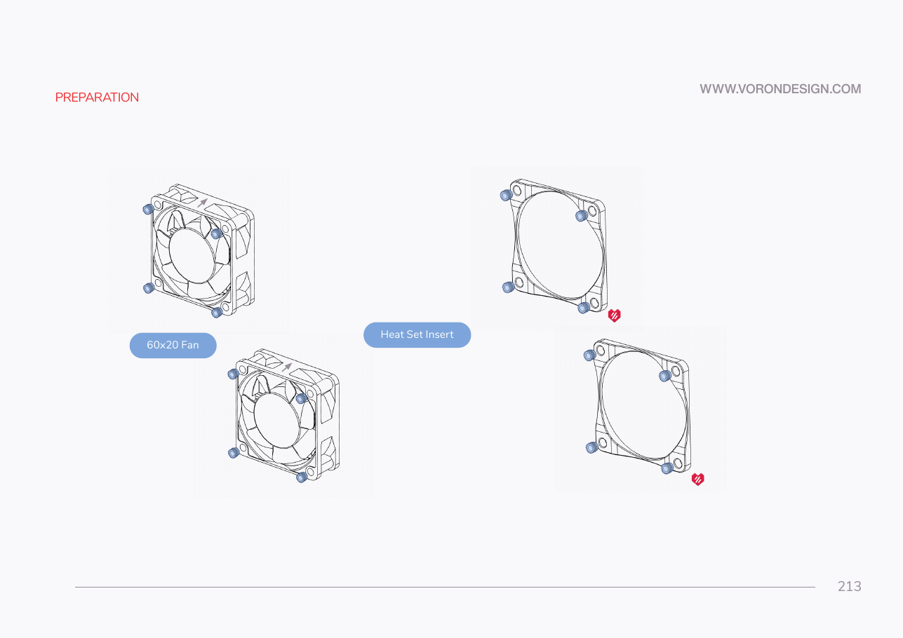
Step 11.3 — Heat-set the bay fans and the fan grill retainers¶
Step 4 of 67 · Chapter 11 — Skirts, panels, Clicky-Clack door, filtration
Tap to enlarge
Parts:
- the two bay fans · already on the bench
-
[a]_fan_grill_retainer×2 · bin 11-fans - M3×5×4 heat-set insert ×16 · Fasteners, Tools & Misc box
Do: Read each fan's airflow arrow on the frame edge. Press four inserts into the corner holes of the face the arrow points away from, then four into each retainer's corner bosses.
Check
Sixteen inserts flush and square, four per fan on its intake face and four per retainer. No fan frame cracked.
What you're looking at
The two 60 × 20 mm fans are the electronics-bay coolers. Each takes four inserts in its corner holes, and so does each printed grill retainer, which stands in for a fan behind the grills of the empty support.
Caution
Rev D+ / LDO: the kit ships exactly two 60×60×20 mm 24 V fans and one 3×2 XH splicer PCB, which joins them into a single "PCB FAN" run. Do not expect four. src · src
Source: Voron manual p.213 · LDO Rev D 350 BOM · LDO wiring guide § Connecting the fans and the LED strip