Step 14.29 — Swap the exhaust cover for the housing
Step 29 of 36 with a helper · Chapter 14 — Calibration and tuning
 Gather for this segment — step 14.29 (~30 min)
Bin 14-exhaust
- filter mount ×2
Tools and consumables
- VHB tape
- 2.5 mm hex key
- 3 mm hex key
Already on the bench
- the exhaust grill and its two M3×12 SHCS
- the cover tabs' two M5 T-nuts and M5×10 BHCS
- the PTFE coupler and the reverse-bowden PTFE
Parts:
- the exhaust grill and its two M3×12 SHCS · already on the bench
- the cover tabs' two M5 T-nuts and M5×10 BHCS · already on the bench
- the PTFE coupler and the reverse-bowden PTFE · already on the bench
- filter mount ×2 · bin 14-exhaust
- VHB tape · consumable
- 2.5 mm hex key · tool
- 3 mm hex key · tool
Do:
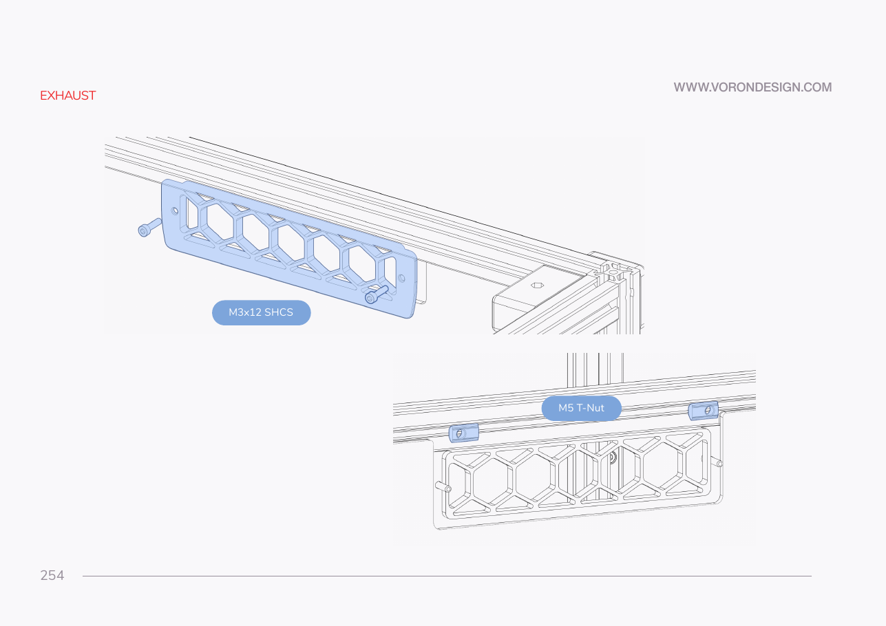
- Machine off. PTFE and coupler out of the cover; unbolt cover and grill, keep all four screws.
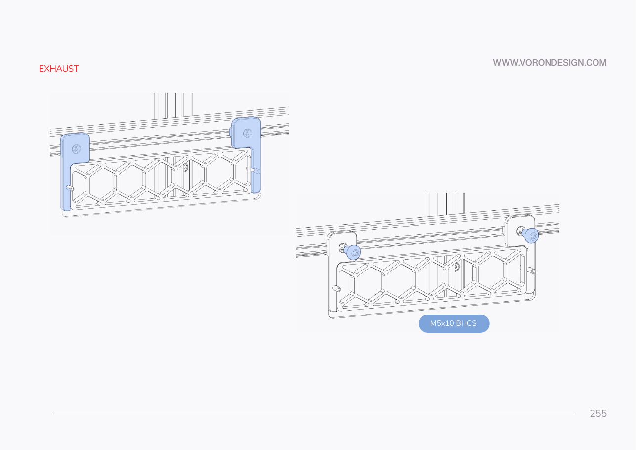
- Hang the grill on both mounts on the same T-nuts, snug.
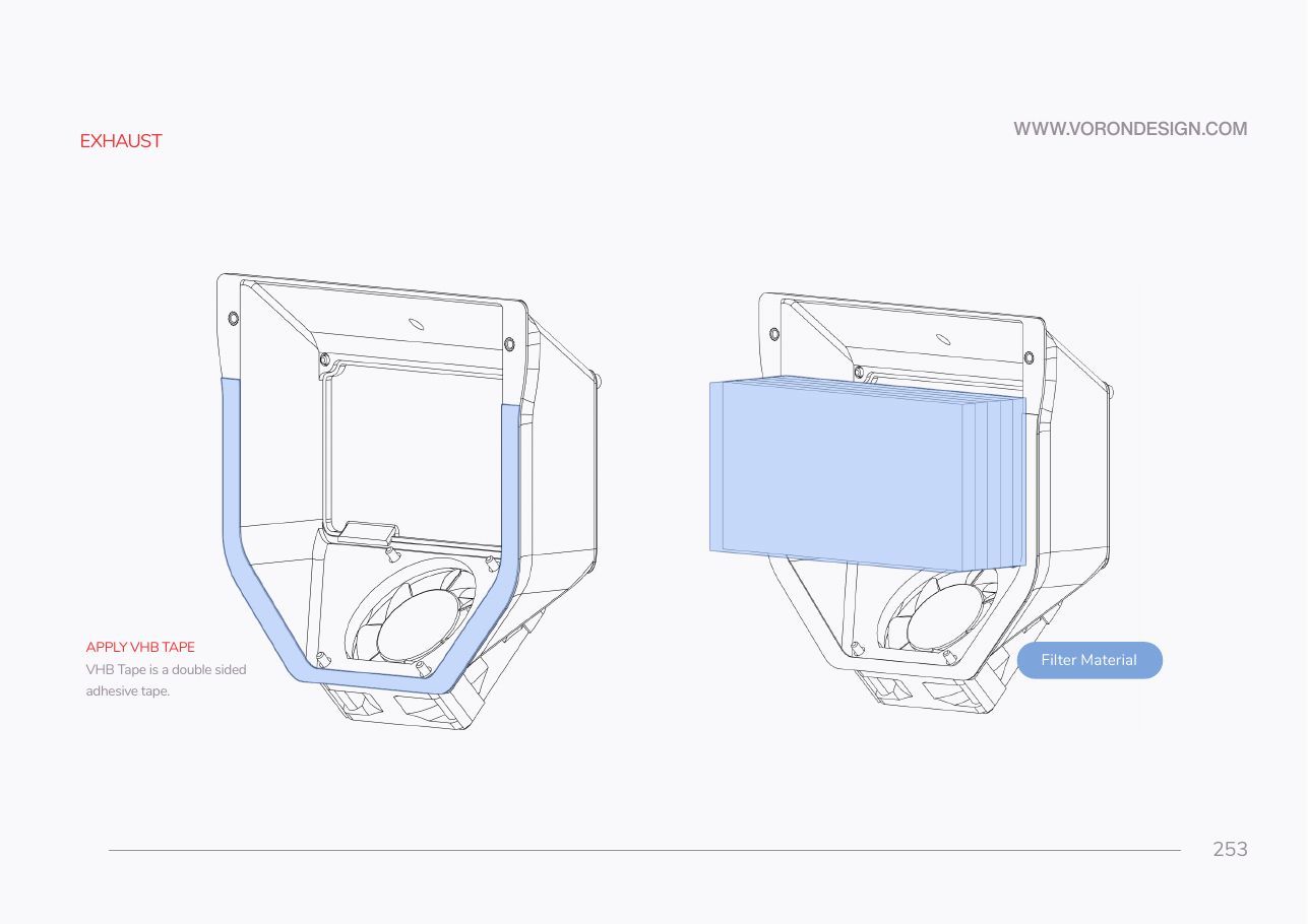
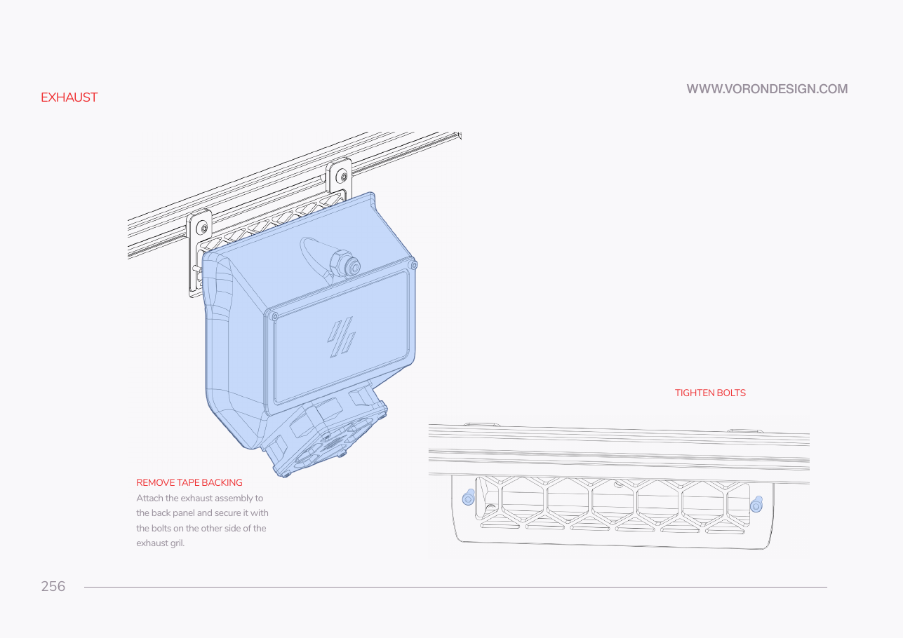
- Tape the housing on; drive both M3×12 from inside.
 Check
The housing sits square over the notch with no light round the tape, grill and mounts are tight, and full XY travel touches nothing.
 Helper Holds the housing square on the panel while the adult drives the two screws from inside.
What you're looking at
The grill sits in the notch, held up by two mounts bolted to the top rear extrusion. The housing is taped to the outside of the panel over it, and the two grill screws pull it tight from inside the chamber.
Caution
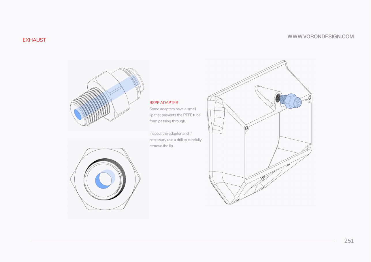
Before taping, pass the fan lead in through one grill opening. Then thread the coupler into the housing's top boss and run the PTFE in through it, looped as p.258 shows (verify on bench).
 Tip
keep the exhaust cover. Refitting it returns the machine to its Ch 11 state if the add-on comes off.
 Good stopping point · ~30 min since the last one
the housing on the back panel, the exhaust cover kept as a spare, the fan lead inside the chamber and unplugged. Leave the tape an hour before anything leans on the housing.
Source: Voron manual p.254 · Voron manual p.255 · Voron manual p.256