Step 14.28 — Build the fan and the filter into the housing
Step 28 of 36 · Chapter 14 — Calibration and tuning
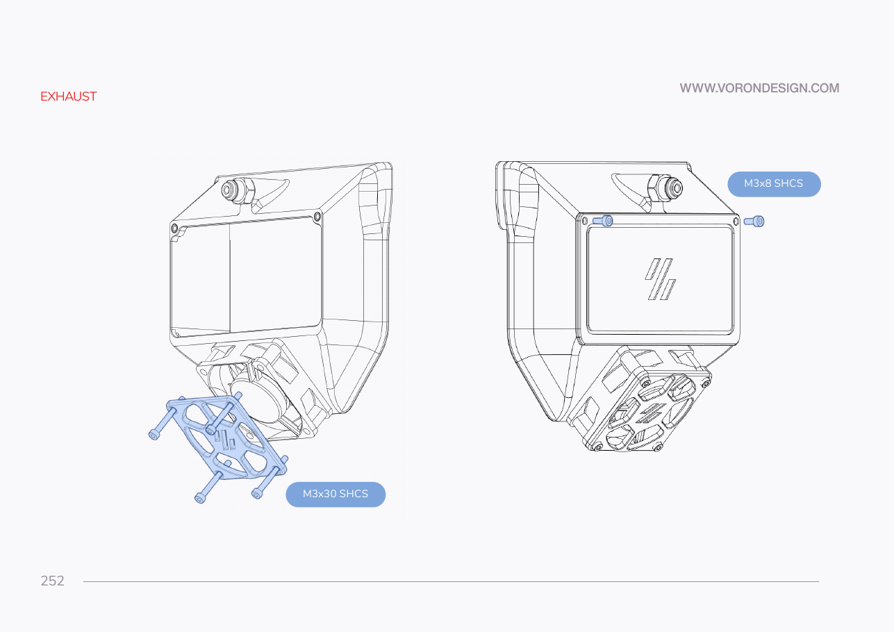
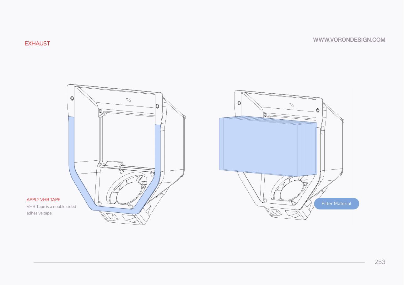
Parts:
- exhaust housing ×1 · bin 14-exhaust
- fan grill ×1 · bin 14-exhaust
- access cover ×1 · bin 14-exhaust
- 24 V exhaust fan ×1 · bin 14-exhaust, bought at Ch 00
- carbon filter mat layer ×2 · bin 14-exhaust, bought at Ch 00
- M3×30 SHCS ×4 · Fasteners, Tools & Misc box
- M3×8 SHCS ×2 · Fasteners, Tools & Misc box
- scissors · tool
- 2.5 mm hex key · tool
Do:
- Bolt fan and grill on with four M3×30, arrow out, lead fed inside the housing.
- Cut two mat layers to fill the filter bay; slide them in.
- Close the access cover with two M3×8.
Check
The fan spins freely by hand, its arrow points out of the housing, and its plug reaches the panel face past the mat.
What you're looking at
The fan sits on the housing's angled bottom face. It pulls chamber air through the grill and the carbon mat and blows it out of the bottom. The access cover closes the filter bay, so the mat can be changed later.
Caution
Two mat layers, not the full stack the Voron CAD draws: PLA and PETG need the airflow more than the filtering. The PLA test at the end of this part decides whether even those two stay.
Good stopping point · ~40 min since the last one
eight inserts set, and the fan, its grill, the mat and the access cover on the housing. The Voron is untouched and still has its exhaust cover.
Source: Voron manual p.252 · Voron manual p.253