Step 00.22 — Understand the rail jigs before you need them
Step 22 of 32 · Chapter 00 — Before you start
Tap to enlarge
Parts:
-
MGN9_rail_guide_x2×2 · bin 00-jigs -
MGN12_rail_guide_x2×2 · bin 00-jigs -
pulley_jig×1 · bin 00-jigs
Do:
- Keep both rail-guide sizes with the jigs; the rails stay bagged now.
- Keep the
pulley_jigin 00-jigs. It sets the A and B motor pulley heights in Ch 04.
 Check
Both guide sizes fitted, the MGN12 on the bare rail at Gate B and both on the extrusion at Step 00.20.
What you're looking at
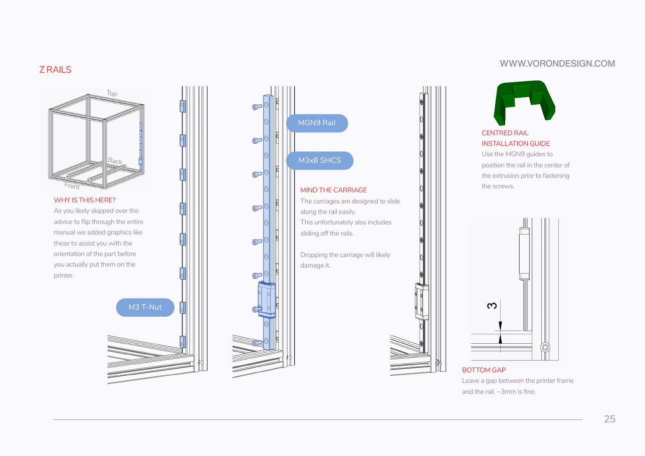
Manual p.25 draws the rail guides in green, its jig colour. A rail guide clips over the 2020 extrusion and the rail and holds the rail centred while you start the screws; the pulley_jig sets how far a pulley sits along a motor shaft.
Caution
Rev D+ / LDO: two rail-mounting rules that override the manual's default from Ch 02 onward. First, do not use the end hole; use the second hole in from each end, per LDO Build Notes p.88. Second, tighten rail screws from the centre outward to pull the rail flush, leaving a ~3 mm gap between frame and rail bottom. src
 Good stopping point · ~40 min since the last one
all seven rails greased, wiped back to bare steel, labelled X / Y1 / Y2 / Z0–Z3 and bagged, and both jig sizes test-fitted. Rail prep is per-rail work, so if you have to stop earlier, stop after a rail is packed, wiped and bagged — never with a carriage half-packed.
Source: Voron manual p.25 · Voron manual p.24 · LDO Build Notes (Rev D) · Voron-2 STLs/Tools