Step 09.34 — Build and mount the bed WAGO breakout¶
Step 34 of 36 · Chapter 09 — Electronics bay
Parts:
- Bed WAGO Mount ×1 (LDO-supplied printed) · Electronics 2 box
- M3×5×4 heat-set inserts ×2 · Fasteners, Tools & Misc box
- 2×2 XH splicer PCB ×1 · Electronics 2 box
- M3×6 BHCS ×2 · Fasteners, Tools & Misc box
- WAGO 221-412 (2-way) ×2 · Electronics 1 box
- M5×10 BHCS ×2 · Fasteners, Tools & Misc box
- M5 T-nut ×2 (verify on bench) · Fasteners, Tools & Misc box
Do:
- Heat-set two inserts into the front face; let cool.
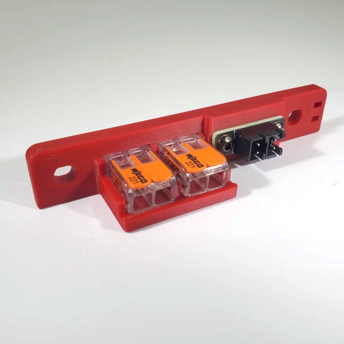
- Screw on the splicer PCB; snap in both WAGOs.
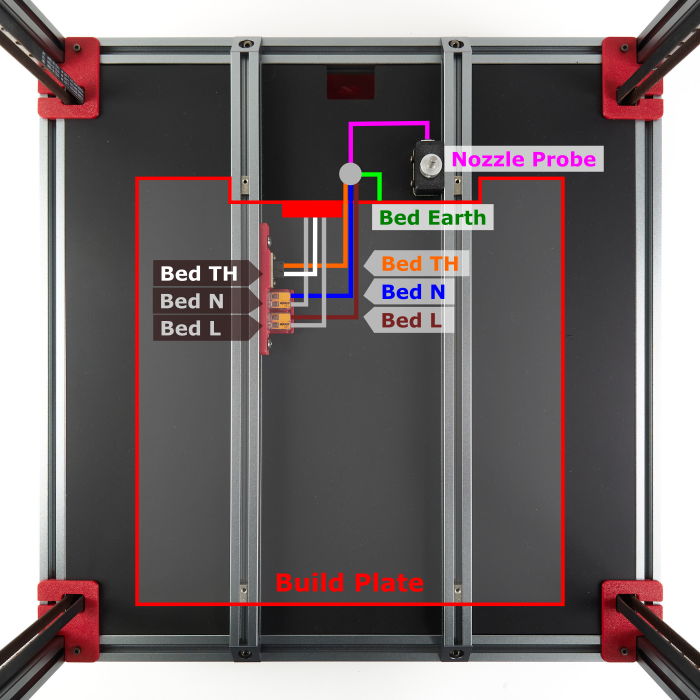
- Bolt it to the left bed extrusion's inner side slot, above the deck under the plate's rear half
(verify on bench).
Check
Inserts flush, splicer PCB solid, both levers free. Mount above the deck, clear of the plate underside; the plate's three leads reach it with slack.
What you're looking at
The bed WAGO mount is a small breakout above the deck, in the chamber under the plate, on the left bed extrusion. The plate's three short leads end here, so the plate lifts off from above; extension leads carry on below deck.
Caution
Rev D+ / LDO: a Rev C+ addition with no manual page. LDO's build-plate mapping puts it above the deck on the left bed extrusion, so the plate detaches from the top: two 2-way WAGOs break out bed L and N, the splicer PCB the thermistor. Nothing goes below the deck here; terminating is Ch 10. src
Good stopping point · ~25 min since the last one
XY endstop PCB in its pod and the pod on the gantry, bed WAGO breakout built and mounted above the deck on the left bed extrusion. The plate's three leads reach it with slack; none of them terminated.
Source: LDO wiring guide § Wiring the bed heater · LDO wiki build-plate mapping · LDO 350 Rev D BOM · image bed_wago_mount.jpg