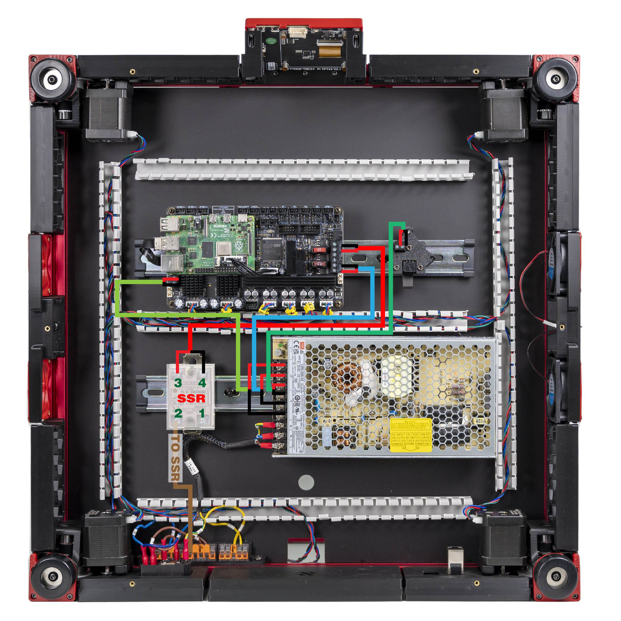
Step 10.10 — Read the SSR terminal numbers before you wire it¶
Step 10 of 80 · Chapter 10 — Wiring and Checkpoint #1
Gather for this segment — steps 10.10–10.16 (~30 min)
Fasteners, Tools & Misc box
- M5 locking washer ×2
- M5×10 BHCS (verify on bench) ×1
- M5 roll-in T-nut (verify on bench) ×1
The Cable Kit box
- SSR to Wago cable ×1
- Bed L extension lead ×1
- Bed N extension lead ×1
- FRAME PE cable ×1
Tools and consumables
- multimeter
Already on the bench
- the Omron SSR on its DIN bracket
- the plate's Bed L, Bed N and BED TH leads and its PE ring terminal
- the bed WAGO mount with its two WAGO 221-412 and the 2×2 XH splicer
- the Bed L and Bed N extension leads, far ends still free
- the Bed L extension lead
- the Bed N extension lead
- the bed PE lead
Parts:
- the Omron SSR on its DIN bracket · already on the bench
Do: Read the SSR body: the pair silkscreened 1 LOAD 2 is the AC switching side, 3 + INPUT 4 − the DC control side. Note which end the yellow indicator LED sits at, and match LDO's photo.
Check
You can point at terminal 1, 2, 3 and 4 without hesitating, and the LED is on the same side as in the photo.
What you're looking at
The SSR is the black brick on the DIN rail: a solid-state relay, so the mainboard can switch a mains bed heater with a small DC signal. Its four screws are two separate circuits, 1/2 the mains it switches and 3 +/4 − the control side.
Note: how LDO tags its cables. Every pre-made lead in the kit is tagged, and the two kinds of tag say different things. A TO … tag names the far end's destination: TO SSR sits at the WAGO end of SSR to Wago; TO MB, TO MB HV and TO TOOLHEAD sit at the PSU ends of the board supply, the HV stepper supply and 24V power. The other end of each of those carries the rail name it lands on — 24V, HV, 24V IN, SSR SIG — not a destination. Read a TO tag as "this cable is going to …", a rail tag as "this is the … rail", then check the connector type and the red/black polarity at both ends. src
Note: the SSR body is also marked EARTH THE MOUNTING RAIL. LDO's build does not run a separate PE to the DIN rail. If your local rules require an earthed rail, that is a mains change — have it specified by whoever signs off your mains work.
Caution
Rev D+ / LDO: "The SSR connection is critical, an incorrect connection can cause catastrophic damage." Nothing else in this chapter carries that warning. src
Source: LDO Rev D photo S4 24 V/SSR mapping · LDO wiring guide § Connecting 24V · Video: Part 8 @1:29:57