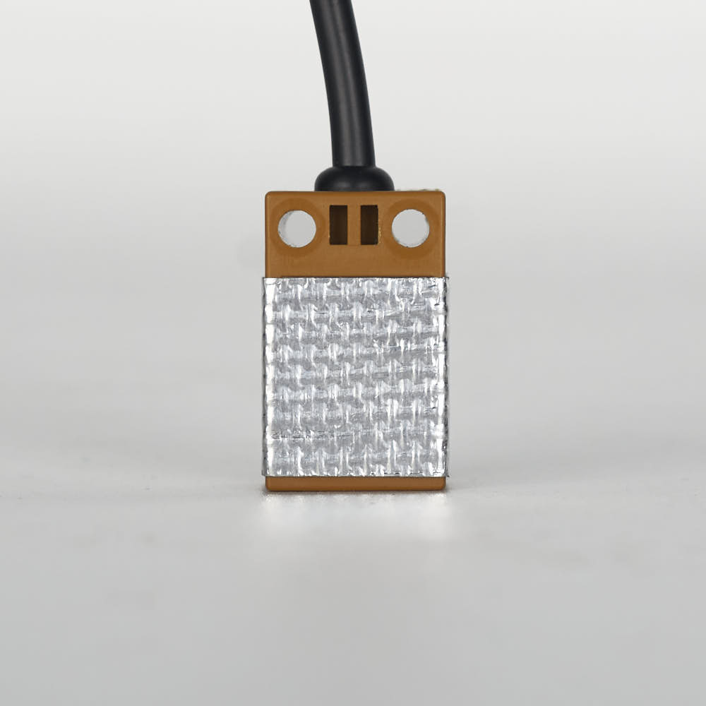
Step 10.30 — Confirm the inductive probe's tape¶
Step 30 of 80 · Chapter 10 — Wiring and Checkpoint #1
 Gather for this segment — steps 10.30–10.34 (~25 min)
The Cable Kit box
- XY endstop cable ×1
- Z endstop cable ×1
Tools and consumables
- tweezers or the supplied 2.5 mm flat screwdriver
Already on the bench
- the XY endstop PCB on the right XY joint
- the nozzle-probe PCB
Parts: none.
Do: Look at the probe on the carriage. Confirm the tape from Step 07.34 is intact on the front and sides. Do not add more tape.
 Check
The sensing face and the back are bare, and the tape does not bulge past the probe's lower rim.
What you're looking at
The inductive probe is the small Omron sensor on the X carriage that senses the metal bed for gantry levelling; it never sets Z=0. Its fibreglass tape went on before it was fitted. This step only confirms it.
Caution
Rev D+ / LDO: the tape shields the probe from hotend heat; it is not a spacer. A second wrap here makes too much, and the probe stops triggering. Torn tape: patch that spot only. src
Source: Voron manual p.143 · LDO wiring guide § Insulating the Z-probe · LDO wiki probe insulation photo