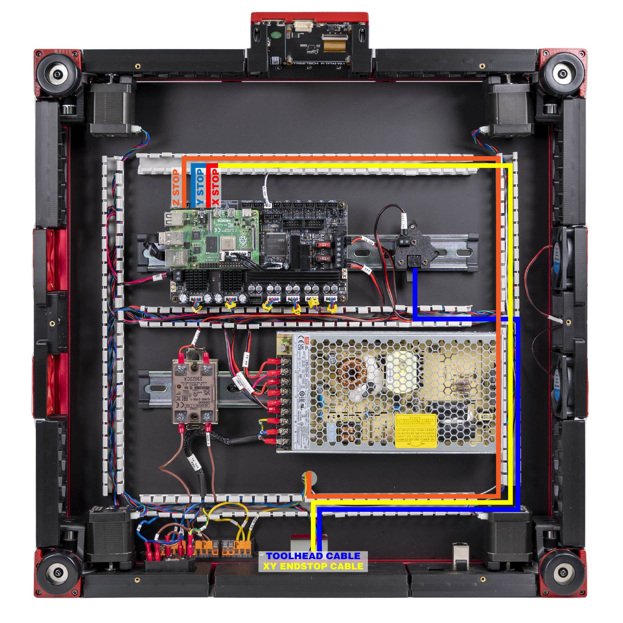
Step 10.33 — XY endstop cable → the gantry PCB¶
Step 33 of 80 · Chapter 10 — Wiring and Checkpoint #1
Parts:
- XY endstop cable ×1 · the Cable Kit box
- the XY endstop PCB on the right XY joint · already on the bench
Do: Plug the 4-pin end into the XY endstop PCB. Leave the two 3-pin ends free; they reach the Leviathan in step 10.45. Dress the cable along the right Y extrusion toward the rear-right, ready for the Y chain.
 Check
The connector is fully home and the cable leaves the PCB without loading the switch bodies.
What you're looking at
The XY endstop pod is the small PCB on the right XY joint carrying both the X and the Y microswitch. X homes to the right and Y to the rear, so the pod sits where both limits are hit.
Caution
Rev D+ / LDO: the kit uses one XY microswitch PCB, not the manual's hall-effect pods. Manual p.162 and p.169 are skipped entirely. src
Source: LDO Rev D photo S6 gantry-cable mapping · LDO wiring guide § Wiring the XY endstop · LDO Build Notes p.162, p.163, p.169