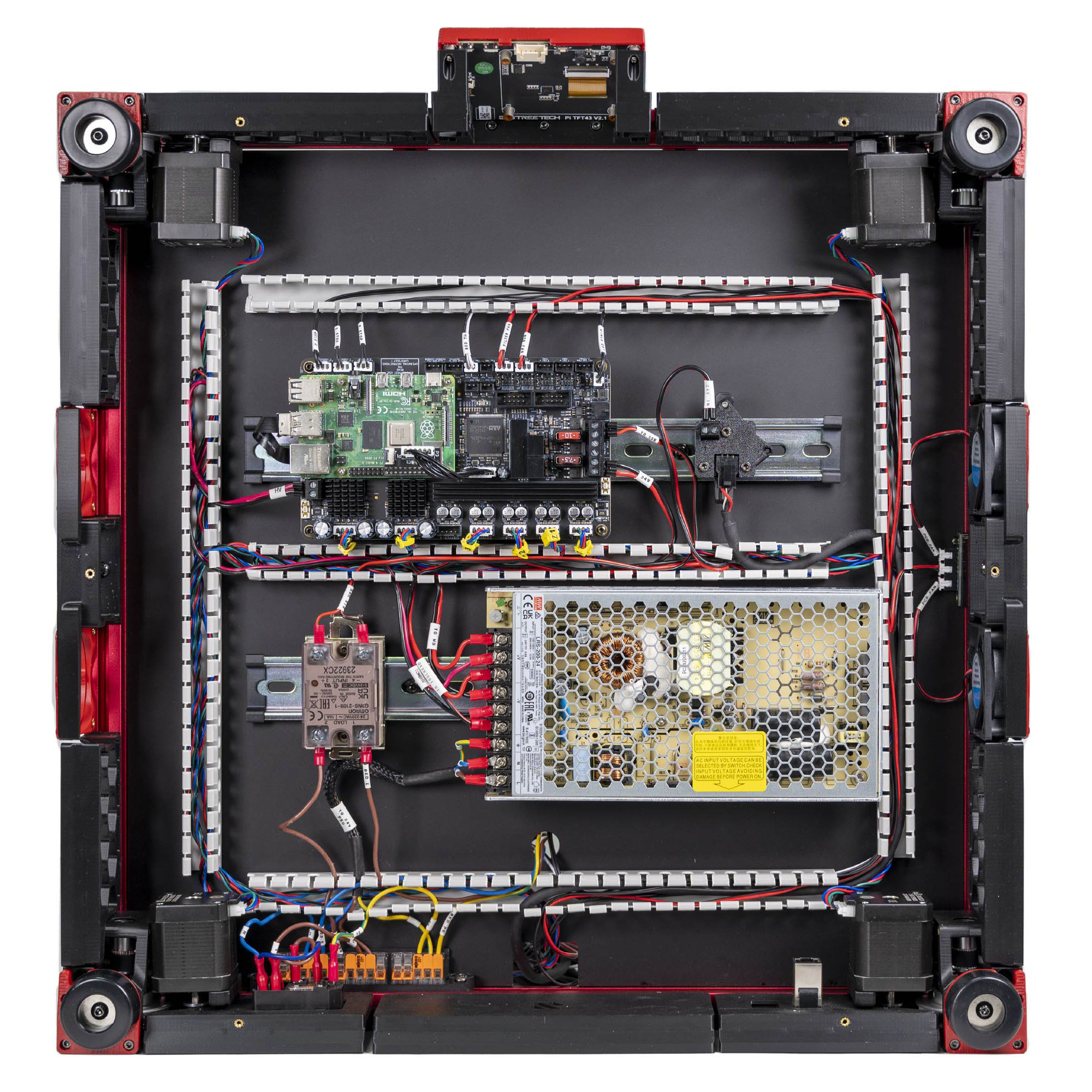
Step 10.48 — Filter fan → FAN3¶
Step 48 of 80 · Chapter 10 — Wiring and Checkpoint #1
Parts:
- FILTER FAN cable ×1 · the Cable Kit box
Do: Plug the board end into FAN3, pin PF9. Route the free end up through the Z-chain notch, not the round hole, toward the Nevermore position at the rear of the chamber. Coil 150 mm of slack there.
 Check
The cable is at the board and the free end is parked where Ch 11 will need it.
What you're looking at
FAN3 is the port reserved for the Nevermore: the recirculating activated-carbon filter that scrubs ASA fumes inside the chamber. The filter itself is built in Ch 11, so only its cable is placed and parked now.
Layout v3
the notch route adds about 44 mm; check the lead has spare during this fit (verify on bench). If it's short, make a longer replacement FILTER FAN lead, same connector (verify on bench); the lead never enters the AC conduit. LDO layout: up through the round deck hole, as LDO's fan mapping shows. LDO § Connecting the fans and the LED strip
Source: LDO Rev D photo S7 fans wired · LDO wiring guide § Connecting the fans and the LED strip