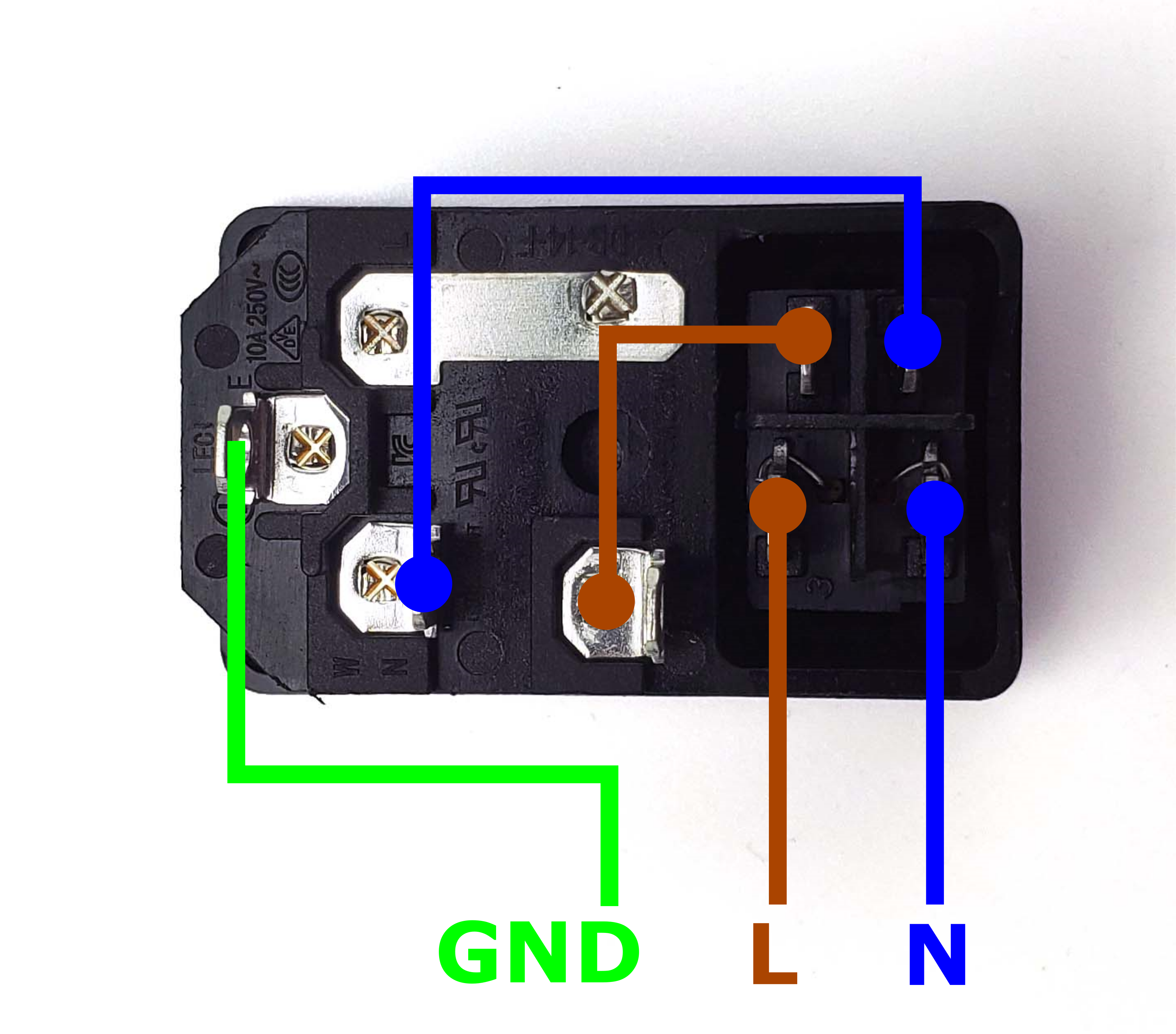
Step 10.5 — Verify the pre-wired inlet before you trust it¶
Step 5 of 80 · Chapter 10 — Wiring and Checkpoint #1
Gather for this segment — steps 10.5–10.9 (~30 min)
The Cable Kit box
- PSU AC cable set, 3 cores ×1
Tools and consumables
- multimeter
- label maker
- PH2 screwdriver
Already on the bench
- the AC inlet module
- the three WAGO 221-415 blocks in their mount
- the inlet module's three pre-wired cores
- WAGO N, L and PE
Parts:
- the AC inlet module · already on the bench
- multimeter · tool
Do: Compare your pre-wired inlet against LDO's diagram: the fuse sits in series with Live; Live and Neutral pass through the rocker; the Earth spade is neither switched nor fused. Three wires leave: brown L, blue N, green/yellow PE.
Check
Meter on continuity, nothing plugged in. Every row of the table matches.
What you're looking at
LDO's internal map of the inlet module: which spade tab feeds which, the fuse in series with Live, the rocker breaking both Live and Neutral. The green/yellow wire is protective earth, the conductor that bonds the metalwork so the machine stays safe to touch.
| C14 pin → wire | rocker | expect |
|---|---|---|
| E → green/yellow | either | beeps |
| L → brown | ON only | beeps |
| N → blue | ON only | beeps |
| L → brown, fuse pulled | ON | open; refit the fuse |
Any deviation from that pattern means the inlet is miswired — stop and fix it before anything else. src
Source: LDO wiring guide § Preparing the inlet · LDO wiki inlet layout diagram