Step 10.58 — Fit the ESD grounding path¶
Step 58 of 80 · Chapter 10 — Wiring and Checkpoint #1
Parts:
- the long supplied grounding cable, ring already on the USB adapter · already on the bench
- M3×8 SHCS ×1 (verify on bench) · Fasteners, Tools & Misc box
- M3 roll-in T-nut ×1 (verify on bench) · Fasteners, Tools & Misc box
- multimeter · tool
Do:
- Confirm: both short-cable lugs under screws, the long cable's ring on the USB adapter.
- Land its free end on the nearest bottom frame extrusion
(verify on bench): anodising scraped, ring on bare metal, M3×8 SHCS into a roll-in T-nut.
 Check
Meter on Ω: extruder motor body → toolboard ground lug < 2–3 Ω; USB-adapter ground lug → C14 earth pin < 2–3 Ω.
What you're looking at
Detail photos: toolboard ground routing · USB-adapter ground point
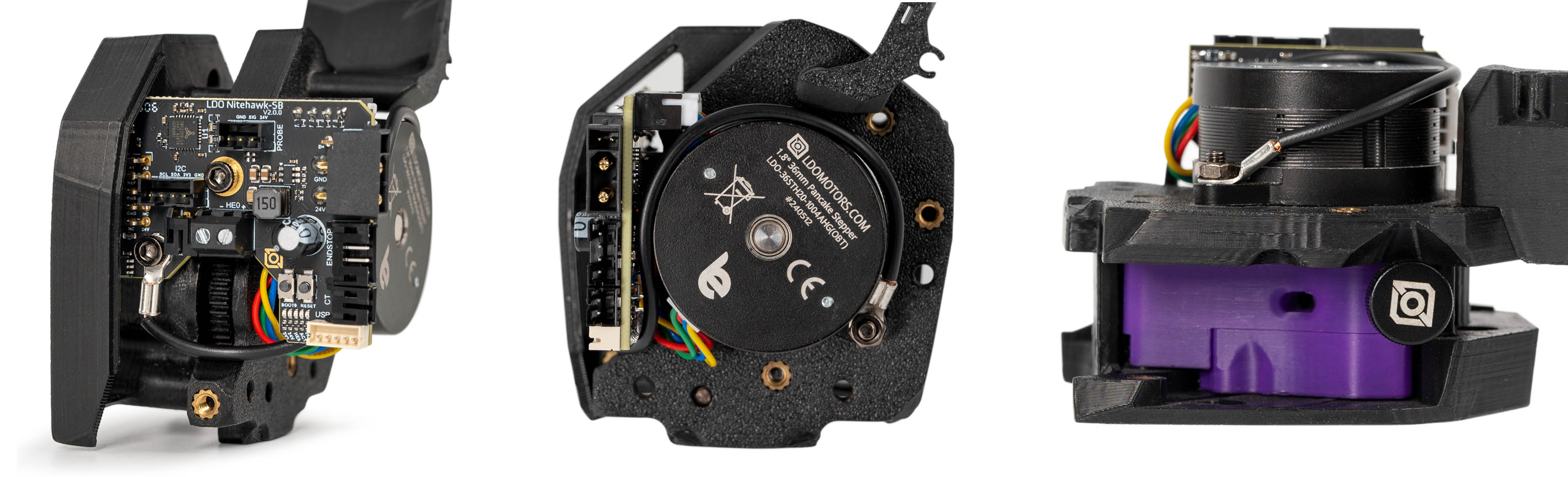
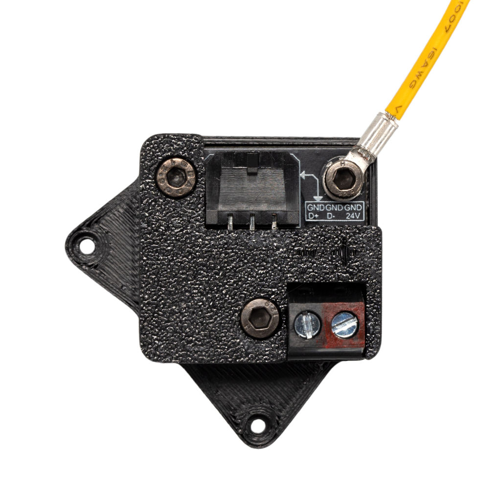
ESD, electrostatic discharge, is the static filament and moving belts build up, and it kills toolboards. The two supplied cables build one continuous path from the extruder motor body, through the toolboard and umbilical, to the USB adapter and out to the earthed frame.
Caution
Rev D+ / LDO: use the supplied grounding cable. LDO: "using larger O ring connectors may cause inadvertent shorting of the PCB boards."
Caution
If your kit did not include the grounding cables, or your board doc predates the update: stop, post the three images above in #ldo_motors on the Voron Discord and wait for LDO's answer before improvising. The scheme was undocumented until the board doc was updated 2026-07-10. src — survey §4.1 ⑤
 Good stopping point · ~25 min since the last one
the three Rev D+ toolhead deviations verified (PH2.0 housings, keyed 2×5 fan-adapter header, V2 partial cover), both ESD grounding cables confirmed and the bay cable landed on the frame, each half continuity-checked (the end-to-end reading waits for 10.67). Toolhead is closed and the umbilical is still loose.
Source: Nitehawk-SB-V2 repo grounding_scheme.jpg · Nitehawk-SB-V2 repo toolboard_ground_routing.jpg · Nitehawk-SB V2 doc § ESD hardening

