Step 14.27 — Set the eight heat-set inserts in the housing
Step 27 of 36 · Chapter 14 — Calibration and tuning
Tap to enlarge
Gather for this segment — steps 14.27–14.28 (~40 min)
Fasteners, Tools & Misc box
- M3×5×4 heat-set insert ×8
- M3×30 SHCS ×4
- M3×8 SHCS ×2
Bin 14-exhaust
- exhaust housing ×1
- fan grill ×1
- access cover ×1
Bin 14-exhaust, bought at Ch 00
- 24 V exhaust fan ×1
- carbon filter mat layer ×2
Tools and consumables
- soldering iron with the LDO insert tip
- scissors
- 2.5 mm hex key
Parts:
- M3×5×4 heat-set insert ×8 · Fasteners, Tools & Misc box
- soldering iron with the LDO insert tip · tool
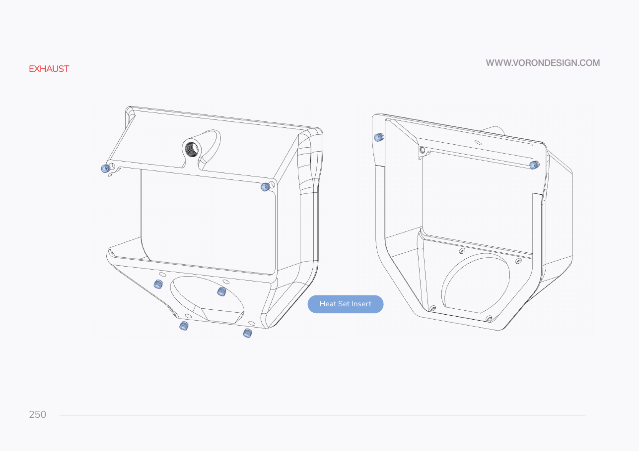
Do: Press an insert into each of the eight bosses p.250 highlights. Part flat, insert square, same tip temperature as every insert before.
Check
Eight inserts flush and square, with no plastic pushed up round any of them.
What you're looking at
The housing takes eight M3 inserts: two on the panel face for the grill screws, two on the outer face for the access cover, and four round the fan opening for the fan and its grill.
Source: Voron manual p.250