Chapter 00a — Mains safety: read before Chapter 09¶
One page per step
Read this chapter one step per page — big pictures, prev/next, and the same tick marks. This page is the whole chapter in one scroll.
Everything you must decide, buy and agree before the electronics bay exists: who is allowed to do the mains work, who is allowed in the room, what meter you need, where the protective earth runs in this machine, and what to do when it goes wrong. Nothing is built here — this chapter exists so that Ch 09 and Ch 10 never stop to ask a question that should already have an answer.
What you're building in this chapter: no hardware — four decisions and one purchase, each of which has to exist before a part goes in. A named person for the mains connections, and a written rule about who is in the room while they are made. A multimeter with a category rating, proved on a live outlet, because Ch 10's Checkpoint #1 is seven measurements and a meter that has quietly died reads every one of them as safe. An RCD/GFCI outlet with a labelled breaker, so the circuit can be killed from outside the room. And a mental map of the parts you will meet in Ch 09–10: the combined AC inlet (socket, switch and fuse in one body), the WAGO lever blocks that fan mains out to three destinations, the Meanwell PSU that makes the machine's 24 V, the solid-state relay that switches mains to the bed heater, and the protective-earth chain that ties the frame, the plate and the PSU back to the wall socket's earth pin.

Time: 0.75–1.0 h hands-on, first build — reading, one shopping decision, one outlet check. No kit parts are touched.
Sessions: 2 × ~30 min
Prerequisites:
- Ch 00 — Before you start, at least through Step 00.8 (the tool table, where the multimeter is a "Buy if not owned" row) and Step 00.30 (the measurement log and your daughter's assigned jobs). This chapter turns both of those into rules.
- Print batches: none. Nothing here is printed, mounted or wired.
- Read this before Ch 09, not before Ch 10. Ch 09 already puts the inlet, the PSU and the SSR into the machine; by the time you open Ch 10 the decisions below are already spent.
Tools
- Digital multimeter — see Step 00a.3 for the minimum spec. This is the one tool in the build with a safety rating, not just a tolerance.
- The multimeter's own test leads, rated at or above the meter's category
- A known-live wall outlet you can reach (for the meter self-test)
Consumables: none.
Printed parts: none. No print batch gates this chapter.
Hardware
| Fastener / part | Qty | Note |
|---|---|---|
| — nothing is consumed in this chapter — | 0 | every mains part stays in its box until Ch 09 |
Read first
- Mains is the only irreversible hazard in this build. Every other safety fact in this manual is stated at the step that needs it. This one cannot be, because the decisions — who wires it, what meter, which outlet — are made weeks earlier. src
- There is no step in this manual where a 13-year-old touches mains wiring. Step 00a.2 names the exact stretches she is not present for, and what she does instead.
- The meter is not optional and it is not a formality. Ch 10's Checkpoint #1 is seven meter measurements on an unplugged machine, and it is the hard gate before the bay closes (survey §5.2 W8).
- If your local rules say a certified person must make the mains connections, that is the whole of Ch 10 Section 1. Decide it now, not with the printer on its back and the WAGOs half-populated.
- Nothing in this chapter overrides a step. Where this chapter and a step disagree, the step wins and the disagreement is a bug — log it in the corrections table in 00-index.md.
- Mirrored images in this chapter are LDO Motors' (LDOVoron2 wiring guide, docs.ldomotors.com), used with attribution; see
assets/remote/00a-mains-safety/SOURCES.txt. Each step keeps the original URL on itsSource:line.
Before the kit arrives¶
Step 00a.1 — Decide who is doing the mains work¶
(no image — see text)
What you're looking at: No parts: a decision about one stretch of the build. The conductors that carry wall voltage are the C14 inlet, the WAGO lever blocks, the PSU's AC terminal block, the solid-state relay, and the bed heater's live lead. Everything else runs on 24 V.
Parts: none.
Do: Read your local rules for who may make mains connections in a dwelling. If the answer is not you, write that down today: build the machine, mount every part, and hand over at 10.8.
The one region that can kill you is Ch 10 Section 1, 10.1–10.16: the C14 inlet, the three-way WAGO bus, the Meanwell LRS-200-24's AC terminal block, the Omron SSR's LOAD pair, and the bed heater's live lead. The Voron community's standard advice is "install the parts and then find a qualified electrician to do the connecting up." Ch 10's own Read first says the same and names the same stopping line. Writing the decision down changes nothing else in the build order.
Check
One line in the build log naming who lands the mains conductors, dated before the kit ships.
Source: Ch 10 — Read first · Voron forum — Mains Wiring Safety · Voron docs — Electrical Wiring
Step 00a.2 — Write the "who is in the room" rule and post it on the wall¶
(no image — see text)
What you're looking at: No parts: a written rule for the two people building this printer. It names the step ranges where only one person is at the machine, and what the other does instead, so the rule is decided in daylight rather than at the bench.
Parts: none.
Do: Write the mains carve-out to your daughter's measurement-log job, post it where you both see it, and say it out loud once before Ch 09.
Step 00.30 gives her the measurement log, and that assignment has no carve-out for mains. The rule, in these words:
- She does not strip, land, tighten or unplug any conductor that is or has been connected to the wall.
- She is not in the room while the mains conductors are being worked on, or while the machine is plugged in with the bay open — Ch 10 Section 1 (10.1–10.16), the whole of Checkpoint #1 (10.17–10.23), and the firmware gate at 12.11 through Checkpoint 12, and the shut-down at 11.67. Those are adult-only.
- She is not beside the machine at any power-on — 10.23, 12.11 and 13.3. One adult, standing to the side, hand on the switch — nobody else within reach of the machine.
- What she does own on those days: the record, and only with the printer unplugged. In the post-power sweeps at 10.74–10.78, once 10.73 has read 0 V and the cord is out of the room, you hold the probes and read each value aloud, and she records it in the log. She never holds a probe. Recording every row is a real job: it is how you catch a row you skipped.
Check
The rule is written, posted, and has been read aloud. Neither of you has to reconstruct it at 22:00 with the printer on its back.
Caution
This rule is not about competence. It is about there being only one pair of hands near a live conductor, and about that pair belonging to the person who can also reach the breaker.
Source: Ch 00 Step 00.30 · Ch 10 Sections 1–2 · Ch 10 Section 8 · Ch 12 Step 12.11 · Ch 13 Step 13.3
Step 00a.3 — Buy a meter that is rated for the job¶
(no image — see text)
What you're looking at: No parts: the meter you will buy. A digital multimeter measures continuity, resistance, DC volts and AC volts. The CAT rating on its face says how large a surge it can survive where you use it, which is not what voltage it can display.
Parts: none.
Do: Buy a meter with CAT III 600 V printed on its face, and leads rated at least the same category. CAT III leaves margin if you ever probe at a panel.
A meter's CAT rating says what size transient it can survive where you are using it, not what voltage it can display; a meter with no category rating, or the wrong one, can fail violently. Fluke's definitions: CAT II is "Single-phase receptacle-connected loads such as appliances and portable tools"; CAT III is "3-phase distribution including single-phase commercial lighting and equipment in fixed locations such as switchgear and polyphase motors." This printer is a receptacle-connected appliance, so CAT II is the category; CAT III is simply the common rating on decent meters. The four functions in the table are the ones Ch 10's Checkpoint #1 asks for.
| Function | Why this build needs it | Used at |
|---|---|---|
| Continuity / beeper | every Checkpoint #1 measurement | 10.17–10.21 |
| Resistance (Ω) | bed heater, thermistors, PE bonding, 24 V shorts | 10.13, 10.74, 10.76, 10.77 |
| DC volts | confirm dead — 0 V across the PSU's +V/−V, held ten seconds, before the DC side is touched; never a live reading | 10.24, 10.73 |
| AC volts, 600 V range | the meter self-test in 00a.4; never used inside the machine | this chapter only |
Two details worth getting right. Resistance range: Ch 10's tool list asks for "at least 2 MΩ", but 10.13 wants to see the bed heater read "well above 10 MΩ" to earth, and 10.76 reads thermistors up to 162 kΩ. A 2 MΩ meter answers the pass/fail (anything higher shows OL, which is the pass), but a meter that ranges to 20 MΩ or more turns a pass into a number you can write in the log. Leads: they carry their own CAT rating and it is the lower of meter and lead that governs. Do not put unrated leads on a rated meter.
Check
Meter on the bench with a printed category rating, leads rated to at least that category, fresh battery, and all four functions tried once.
Source: Fluke — IEC category ratings · Ch 00 Step 00.8 · Ch 10 — Tools
Step 00a.4 — Test the meter before you trust it, and again after¶
(no image — see text)
What you're looking at: The meter, its two test leads, and a wall outlet you know is live. Live–dead–live means proving the meter works immediately before and immediately after the measurement that matters. A dead meter reads no voltage on a live conductor.
Parts:
- tool: multimeter with its rated leads
- tool: a known-live wall outlet
Do: Prove the meter live–dead–live before you trust any dead reading, and short the probes to check continuity, leads and battery.
A meter that has quietly died reads "no voltage" on a live conductor, which is the most dangerous reading in electrical work. A flat battery or a broken lead does it. Prove the meter on a known-live source, take your measurement, then prove it again on the same source: if it failed in between, you find out before you act on the reading. Do it in this order the first time you use the meter, and every time you are about to touch something you have declared dead:
- Live — AC volts on a wall outlet you know is on. It should read your nominal mains voltage.
- Dead — the measurement you actually care about.
- Live — back to the same outlet. Same reading as step 1.
Then the bench self-tests you will use constantly: on continuity, short the two probes tip to tip — it must beep and read near 0 Ω; wiggle each lead at both ends while it beeps — a dropout is a broken lead. Confirm the battery symbol is not showing. If the meter has a fused current jack, check the fuse now rather than discovering it during a measurement.
Check
Live–dead–live done once end to end. Probes shorted → beep, near 0 Ω, no dropout when the leads are wiggled. No low-battery symbol.
Caution
Step 10.17 opens Checkpoint #1 by shorting the probes for exactly this reason. That is the short version of this step; this is the long one, and it is the one to use before you conclude anything is dead.
Source: NFPA 70E live–dead–live practice · Ch 10 Step 10.17
Step 00a.5 — Put the printer on an RCD/GFCI outlet you can reach¶
(no image — see text)
What you're looking at: The wall outlet the printer will live on, and the breaker that feeds it. An RCD, a GFCI receptacle or GFCI breaker in a US house, compares the current on live with the current on neutral and cuts the supply when they differ.
A residual-current device compares live and neutral current and cuts the supply when they differ, which is what happens when current is leaving through a person or through the frame. RepRap's safety page is blunt about it: "If not compulsory in your country, a 20mA resident current device (RCD) shall be installed on your electrical installation." In a US house that is a GFCI receptacle or a GFCI breaker, and monthly TEST/RESET is for the life of the printer: a GFCI that does not trip on its own test button is a dead GFCI. The PSU alone draws about 4 A at 115 VAC, and the AC bed heater is a much larger load again — the Omron SSR that switches it is rated 10 A.
Parts: none.
Do:
- Press TEST, confirm power cuts, then RESET. Repeat monthly.
- Label the breaker that feeds it, so the circuit can be killed from outside the room.
- Do not share the circuit with a space heater or microwave.
Check
Outlet trips on TEST and resets. Breaker identified and labelled. You can reach that breaker without passing the machine.
Caution
No working GFCI, no plug-in. The printer runs only on a GFCI receptacle or GFCI breaker. One that does not trip on its own TEST button is dead: replace it before the machine is plugged in. The PSU draws about 4 A and the AC bed heater far more, so nothing else heavy shares the circuit.
Source: RepRap — Safety · Mean Well LRS-200 spec sheet · Ch 09 Step 09.17
Good stopping point · ~30 min since the last one
this is the chapter's first segment. Decisions made and written down, meter ordered or found and self-tested, outlet chosen and labelled. Nothing is open, nothing is wired, and no kit box has been touched. Do not start Ch 09 before finishing the rest of this chapter; the earth chain below is what Ch 09's placement decisions assume.
The earth chain, the fuse and the terminals¶
Step 00a.6 — Learn the protective-earth chain in this build¶
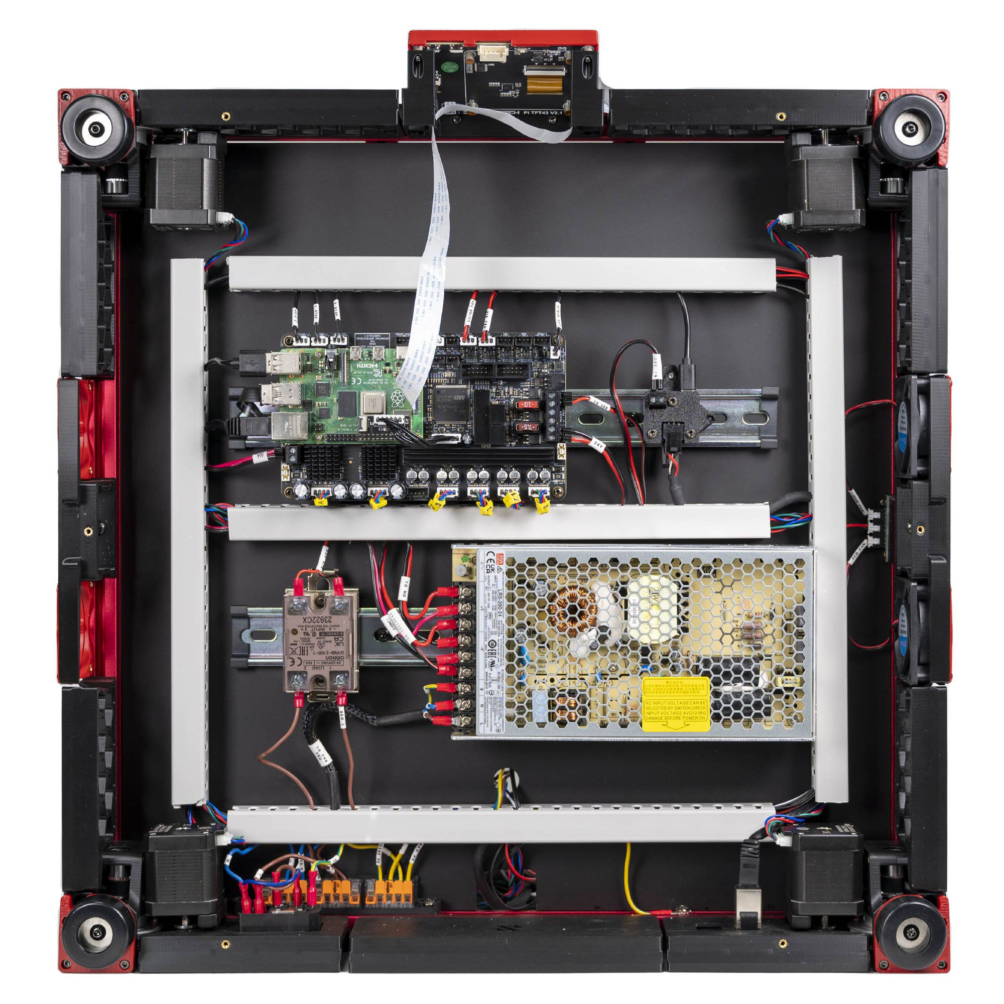
What you're looking at: LDO's photo of the finished bay. Every branch of the protective earth chain is in this one frame: the inlet, the yellow/green WAGO block, the PSU's earth screw, the ring terminal on a frame extrusion, and the lead to the build plate.
Parts: none.
Do: Learn the five protective-earth branches in the table below, and where each is verified, before you meet them in Ch 09 and Ch 10.
Protective earth (PE) is the conductor that makes the machine safe to touch: if a live conductor ever reaches the frame, the bed or a motor can, PE gives that current a path with far less resistance than you, and the fault current trips the breaker or the RCD. The diagram lays out the whole mains path end to end alongside all five PE branches, and which pole the fuse and rocker switch each sit in. Voron's electrical page is explicit that this is not optional on an AC-bed machine — "If using an AC powered bed, be sure to ground the bed regardless of if the assembly manual specifies it or not", and "Grounding the frame is recommended." RepRap adds the constraint people get wrong: "Earth shall be connected to a valid earth, never on plumbing."
| Branch | Runs from → to | Made at |
|---|---|---|
| Supply | wall socket earth → C14 E pin, through the C13 cord. Never switched, never fused | 10.5 |
| Bus | C14 E → the yellow PE WAGO (one of three 5-way blocks) | 10.7, 10.8 |
| PSU | PE WAGO → the Meanwell's ⏚ terminal — the innermost of its three AC screws, next to −V. Order from the outer end is L, N, ⏚ (LRS-200 datasheet: 1 AC/L, 2 AC/N, 3 FG) | 10.9 |
| Frame | PE WAGO → the rear frame extrusion between the mains WAGO mount and the deck notch (layout v3; on LDO's layout, right of the notch), ring terminal sandwiched between two M5 locking washers on bare metal | 10.16 |
| Bed | build plate → PE WAGO, ring terminal on the plate's own M4×6 BHCS + serrated washer | 03.6, 10.12, 10.15 |
A sixth path is not protective earth but shares the same bus at the far end: the ESD ground from the extruder motor body to the toolboard, fitted at 10.58. It is why the extruder can appears in the earth-bonding table.
The whole chain is proved in one sweep at 10.77: from the C14 earth pin, the PE WAGO and PSU ⏚ read < 1 Ω, the frame PE lug and the plate's M4×6 PE screw read < 1 Ω, a far frame corner < 2–3 Ω, and the extruder motor body a few Ω or less — while the bed heater's L and N, and the +24 V side of the rail, read OL. The rail's −V / GND side reads a few Ω on purpose — that is the ESD bond from 10.58, and 10.74 and 10.77 both expect it; do not go hunting a reversed ferrule for it.
Check
You can draw the five branches from memory and say where each is verified.
Caution
Rev D+ / LDO: the bed's PE screw is already fitted to the plate and is an M4×6 BHCS, not the M3×6 the official manual asks you to supply. Verify it is tight at Step 03.6; do not remove it and refit it. Its serrated washer is what bites through the surface to make the bond. src
Source: Voron docs — Electrical Wiring · RepRap — Safety · Mean Well LRS-200 spec sheet — terminal pin assignment · LDO wiring guide § Frame PE · image: LDO VS9_Final.jpg · Ch 10 Step 10.77
Step 00a.7 — The SSR is marked "earth the mounting rail" and this build does not¶
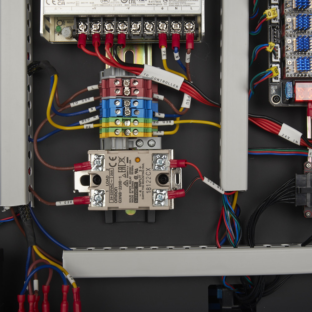
What you're looking at: The solid-state relay on its bracket, with the wording on its body legible: 1 LOAD 2, 3 + INPUT 4 −, and EARTH THE MOUNTING RAIL. An SSR is a semiconductor switch with no moving contacts; here it switches mains to the bed heater.
Parts: none.
Do: Before Ch 09, settle who decides whether the SSR's EARTH THE MOUNTING RAIL marking must be honoured on this build. LDO's build does not run a PE conductor to the DIN rail.
The photo is from LDO's Rev C guide, so the relay in it is the 20 A G3NB-220B-1 and the bus behind it is DIN terminal blocks; your Rev D kit ships the 10 A G3NB-210B-1 and WAGO 221 blocks, and carries the same marking. 10.10 records the marking as you read it off the body. Understand the gap before you are standing in front of it:
- The SSR is an Omron G3NB-210B-1 — 24–220 VAC 10 A on the 1 / 2 LOAD pair, 5–24 VDC on the 3 + / 4 − INPUT pair (09.17). It bolts to a stamped metal bracket which clips to a DIN rail, and that rail bolts to a frame extrusion at 09.5.
- So the rail is bonded to the frame, and the frame is earthed at 10.16 — but through anodised aluminium and steel screws, incidentally. Ch 10.16 tells you to scrape the anodising under the frame PE washer precisely because anodising is an insulator. An incidental bond through two more anodised interfaces is not the same thing as a PE conductor, and it is not a compliance argument.
- Ch 10 states the consequence plainly: if your local rules require an earthed rail, that is a mains change and it belongs to whoever signs off your mains work — not to a decision you make at the bench.
Two more facts from Omron's own datasheet that change how you handle this part. The standard G3NB has no terminal cover — Omron's note is that "If you need a terminal cover, please use the G3NA-240B or similar product" — so four mains-carrying screw terminals sit exposed in your bay until Ch 11 closes it. And the relay's internal snubber leaks: "A leakage current flows through a snubber circuit in the G3NB even when there is no power input. Therefore, always turn OFF the power to the input or load and check that it is safe before replacing or wiring the G3NB."
Check
You can state what the marking asks for, what this build does, and who decides whether that is acceptable where you live.
Omron's caution for this relay
"Be sure to conduct wiring with the power supply turned OFF" and "Do not touch the G3NB's main circuit terminals immediately after the power is turned OFF." Ch 10 already sequences it that way: every mains connection is made with the cord in another room, and 10.73 measures 0 V for ten seconds first.
Source: Omron — Solid State Relays G3NB datasheet (J164-E1) · image: LDO SSR_Close_Up.jpg · Ch 10 Step 10.10 · Ch 09 Step 09.17
Step 00a.8 — Ferrules and the no-whisker rule¶
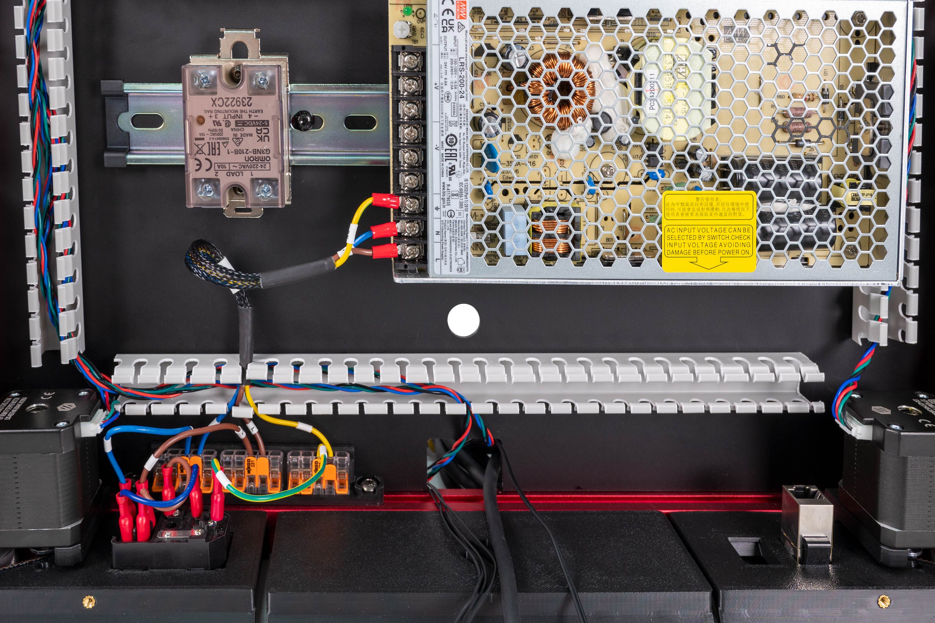
What you're looking at: Two kinds of mains terminal. The PSU's three screw terminals each take a stranded core crimped into a red ferrule, a sleeve that turns loose strands into one tube the screw can clamp. The orange WAGO 221 lever blocks need no ferrule.
Two kinds of terminal carry mains in this machine and they want opposite things. Screw terminals — the Meanwell's L/N/⏚ block, L, N, ⏚ from the outer end, and the SSR's LOAD 1 / LOAD 2 — clamp a stranded core against a metal plate; strands splay, one escapes the clamp, and you are left with a reduced contact area that heats. The kit ships VE0508 ferrules for exactly this, five of them counted in Ch 09's hardware table and used in Ch 10. WAGO 221 lever terminals — the three 5-way N / L / PE blocks — clamp the core themselves; the failure there is not splaying but escaping, and 10.8 gives the test: tug each core hard, and confirm no copper is visible outside any port. A whisker of exposed strand next to a live terminal is the failure mode.
On conductor size, Voron's electrical page sets the floor: "Use at least 18 AWG (0.75 mm²) for mains AC wiring, even better would be 16 AWG (1.25 mm²)." Every mains conductor in this kit arrives pre-made; the number matters if you ever lengthen or replace one.
Parts: none.
Do: Learn which terminal takes which, from the two rows below. Screw terminals get a crimped VE0508 ferrule; WAGO 221 lever terminals take bare stranded or ferruled core to the stop, with no copper visible outside any port.
Check
Ferrules found in the kit before Ch 10 starts, and you know which terminals take one, which take bare core, and the pull-and-look test.
- Screw terminals (the PSU's L / N / ⏚ block, the SSR's LOAD 1 / LOAD 2): a crimped VE0508 ferrule on every stranded core, so no strand escapes the clamp.
- WAGO 221 levers (the three 5-way N / L / PE blocks): core to the stop, lever shut, then tug each core hard and look: no copper outside any port (10.8).
Caution
No whiskers. A strand of exposed copper beside a live terminal is the failure mode: if one shows, re-terminate that core. Mains conductors are at least 18 AWG (0.75 mm²); every one in this kit arrives pre-made, so this matters only if you lengthen or replace one.
Source: Voron docs — Electrical Wiring · image: LDO S3_wago_PSU.jpg · Ch 09 — Hardware · Ch 10 Step 10.8, Step 10.9
Step 00a.9 — Strain relief: nothing may pull on a terminal¶
(no image — see text)
What you're looking at: No parts: a routing rule. Everything here keeps load off a termination: the wire ducts that carry the mains run below deck, the anchor at the deck opening, and the zip ties at both ends of every drag chain.
A terminal is a connection, not an anchor. RepRap's rule is the one to hold: "all wires ends of moving wires and static power wires shall be secured just aside the connection, in order to release any load on connexion." In this build that means the mains run goes inside a wire duct, not across open deck (10.8), the deck opening is strain-relieved (10.69), and every drag chain is zip-tied at both ends so the chain — not the connector — takes the motion (10.66). Ch 10's own warning is that cables pulled tight "will survive assembly and fail in three months".
The same page sets the end state for the whole electronics bay: "All connections of mains (110/230V) shall be physically protected and you shall not be capable to access them even if you try." That is what the bottom panel and the skirts in Ch 11 Part A are for, the AC conduit's lids just before the dead meter sweep (10.80), and the DC duct covers once Ch 13 has driven every motor, heater and fan (Step 10.71). Closing the machine is a safety step, not a cosmetic one — which is exactly why Ch 11 is not allowed to start until Checkpoint #1 has passed.
Parts: none.
Do: Route the mains run inside a wire duct, strain-relieve the deck opening, and zip-tie every drag chain at both ends, so the duct or the chain takes the pull, never a terminal.
Check
You can name the three places this manual anchors a cable near its termination, and why Ch 11 makes the mains inaccessible.
- Mains run inside a wire duct, never across open deck: 10.8.
- Deck opening strain-relieved: 10.69.
- Every drag chain zip-tied at both ends, so the chain takes the motion: 10.66.
Caution
A terminal is a connection, not an anchor. A cable pulled tight survives assembly and fails in three months. The end state is mains you cannot touch even if you try: AC lids at 10.80, bottom panel and skirts in Ch 11 Part A. Ch 11 does not start before Checkpoint #1 passes.
Source: RepRap — Safety · Ch 10 Step 10.69 · Ch 11 — Read first
Step 00a.10 — The fuse in the inlet, and what it does not protect¶
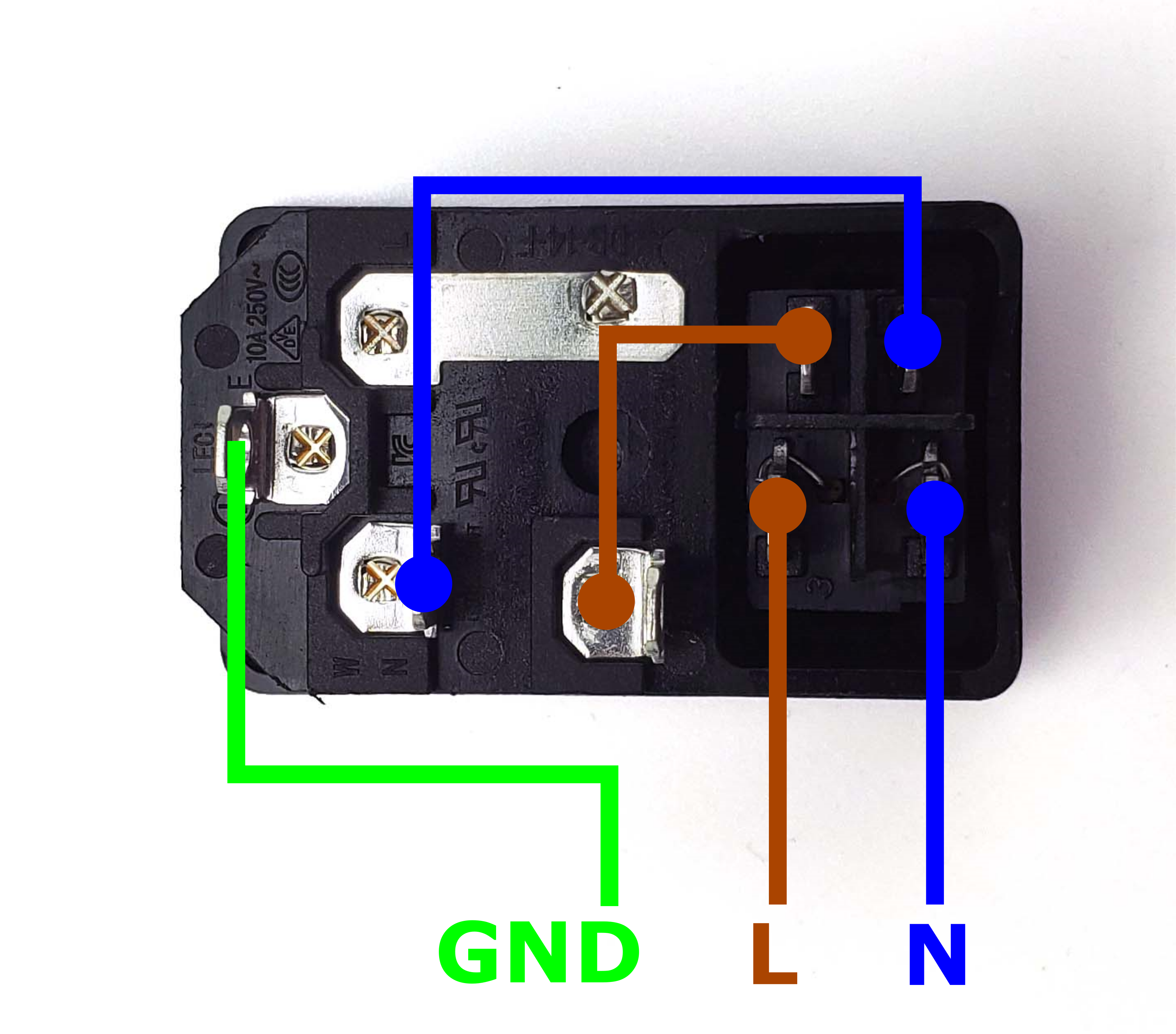
What you're looking at: LDO's diagram of the combined AC inlet: one moulded body carrying the C14 socket where the cord plugs in, the illuminated double-pole rocker switch, and a pull-out fuse drawer. C14 is the male inlet on the machine, C13 the socket on the cord.
Parts: none.
Do: Learn the inlet's three properties, because 10.5 asks you to prove all three with the meter. Keep the fuse at the rating supplied and never fit a larger one.
The kit's AC inlet is a single module — C14 socket, illuminated rocker switch and fuse drawer in one body — not the official manual's separate filtered inlet plus rocker (09.11, 10.4). The three properties:
- The fuse is in series with Live only. Pull it and the L path opens even with the rocker on.
- The rocker switches both L and N. RepRap's requirement — "You always shall be capable to unpower totally the printer, so the printer power switch shall be on the mains" — is met by this module, and only because both poles are switched.
- The Earth spade is neither switched nor fused. It goes straight through. That is correct and it is what makes PE a protective conductor rather than a circuit.
What the fuse is for: Omron's datasheet for your SSR says "The G3NB may rupture if a short-circuit is applied to it. To protect against short-circuit accidents, install a protective device, such as a quick-burning fuse, on the power supply line." The inlet fuse is that device. What it is not for: it does not protect a person. A fault current small enough to kill will not blow a mains fuse — that is the RCD's job (00a.5) and the PE chain's (00a.6). Never fit a larger fuse to stop nuisance blowing; a fuse that keeps blowing is reporting a fault. LDO does not publish the fitted value, so read it off the drawer.
Check
You can find the fuse drawer with the machine upright, and its rating is written in the build log (verify on bench).
Source: Omron — G3NB datasheet (J164-E1) · RepRap — Safety · LDO wiring guide § Preparing the inlet · image: LDO inlet_layout.png
The two rituals, and the bad day¶
Step 00a.11 — Know the two power-on rituals before either one arrives¶
(no image — see text)
What you're looking at: No parts: two scripted sequences, read now so neither is improvised. Checkpoint #1 is meter measurements on a completely unplugged machine followed by one deliberate plug-in. The hand-on-the-switch ritual is a ten-second listen with the chamber cleared.
Why the rituals are written this way. Nothing is measured live: the PSU's +V/−V screws share an uncovered block with live L and N, so its 24 V is proved by the boards' LEDs at 12.11, and the only DC-volts readings in the build are the confirm-dead 0 V at 10.24, 10.73 and 11.67. 12.11 is the first time the Leviathan, the Pi and the toolboard are energised, so the hand-on-the-switch ritual belongs there, not only in Ch 13; Step 13.1 formalises the cleared chamber, and 13.3 repeats the ritual on the closed machine before the first motion. The bay is open by design between Checkpoint #1 and Ch 11: 10.71 leaves the DC duct covers off, and the AC lids that go on at 10.80 cover the mains leads only; the WAGO blocks, the PSU's terminal block and the SSR's screws stay exposed until Ch 11. Voron's page states the general form: "Never plug or unplug any device while the printer is powered", and "Always double check to make sure your printer is unplugged and the capacitors in the power supplies have discharged before touching any wire or terminal." LDO's framing of the whole section: "Incorrect wiring of AC/mains can be dangerous — therefore, always double check your work, and then triple check it once more."
Parts: none.
Do: Read both rituals below, end to end, now. Before the bay closes, the machine is energised at exactly two steps, 10.23 and 12.11. Ch 11 Part A starts by unplugging it.
Check
You can recite both rituals and name the two steps where this machine may be live with the bay open, 10.23 and 12.11.
- Ritual 1 · Checkpoint #1 (10.17–10.23): Cord out of the room, meter the dead machine: colour groups shorted, L / N / PE isolated, switch switching, SSR open, selector re-read. Then one plug-in: rocker off, inlet, then wall, step back, rocker on. One hand on the switch, the other behind your back, no meter. Rocker lit, PSU LED green, ten seconds of look, listen, smell. Off, unplug, cord out of the room.
- Ritual 2 · Hand on the switch (12.11, again at 13.3): Chamber clear, extinguisher within arm's reach. Stand to the side, hand on the rocker, switch on, hand stays ten seconds: PSU LED green, Pi and toolboard LEDs lit, no click-cycling, buzz or smell. Anything wrong: switch off at once.
Caution
Bay open = hands out. Until Ch 11 closes the bay, the machine is live with the bay open only at 10.23 and from 12.11 to Checkpoint 12, hands out of the bay. To look or touch: power off, unplug, read 0 V held ten seconds, as at 10.73. Ch 11 Part A opens with exactly that, at 11.67.
Source: LDO wiring guide § Checkpoint 1 · Voron docs — Electrical Wiring · Ch 12 Step 12.11 · Ch 13 Step 13.3 · 00-index — build order
Step 00a.12 — Decide now what you do when it smokes, trips or bites¶
(no image — see text)
What you're looking at: No parts: five agreed responses. Each row's Do this first removes energy from the machine; the Then column points at the existing step that owns the diagnosis, so nothing here is improvised.
Parts: none.
Do: Agree these five responses before you need one. Every fix below is the branch an existing step already owns; none of them is improvised here.
| What happens | Do this first | Then |
|---|---|---|
| Breaker or RCD trips the moment you switch on | Switch off at the wall, unplug, leave it off | RCD tripping is an L-or-N-to-earth fault; a breaker is L-to-N. Redo 10.18–10.19 |
| Smoke, a hot smell, buzzing or click-cycling | Switch off at the wall, not the rocker, and unplug | Do not open the bay until 10.73 reads 0 V held ten seconds. Suspect a strand outside a terminal, or the PSU selector (10.2, 10.22) |
| A temperature climbs with nothing commanded | Cut power at the switch | Ch 13's what-if table calls this a heater energised through a wiring fault — back to Ch 10, do not "just watch it" |
| SSR reads short LOAD 1 → LOAD 2 unpowered | Do not energise the machine | A solid-state relay that reads short is dead and the bed would be permanently live. Replace it (10.21, 10.78) |
| Someone is shocked or stuck to the machine | Do not touch them. Kill the circuit at the breaker you labelled in 00a.5 | Then emergency services. Any shock, however small, ends the session — the machine stays unplugged until the PE sweep at 10.77 has been redone |
Two standing rules on top of the table. Never re-energise a circuit that tripped without finding out why — a second trip is not new information and it is not a test. And keep the extinguisher from Step 13.1 permanently by the machine, not just on startup day: RepRap's position on unattended printing is that "No printer shall remain unattended", and this one runs multi-hour ASA prints in a hot chamber. No Voron or LDO source specifies an extinguisher class. Buy an ABC extinguisher: A covers burning plastic, C covers live electrical equipment (NFPA 10 classes). Check the label shows the C before it goes by the machine.
Check
All five responses agreed out loud, the breaker labelled, and the extinguisher in reach of the machine rather than in a cupboard.
Source: RepRap — Safety · Ch 13 — What if · Ch 10 Steps 10.19, 10.21, 10.73
Good stopping point · ~25 min since the last one
the chapter is read and nothing is half-done, because nothing was started. The only durable outputs are the posted room rule, the labelled breaker, a tested meter and five agreed responses. Do not carry on into Ch 09 in the same session if you are tired; Ch 09 ends with the machine on its back and the bay open.
Checkpoint 00a¶
Do not open Ch 09 until every line is ticked.
- Decided and written down who lands the mains conductors in Ch 10 Section 1, and whether that is a certified person.
- The "who is in the room" rule is written and posted: adult-only for Ch 10 Steps 10.1–10.16 and 10.17–10.23, Ch 12 Step 12.11 through Checkpoint 12, Ch 11 Step 11.67 and Ch 13 Step 13.3; on the unplugged sweeps 10.74–10.78 she only records the readings while the adult holds the probes.
- Multimeter on the bench with a printed CAT rating (CAT III 600 V or better), matching leads, continuity, Ω, DC V and AC V all found.
- Meter proved live–dead–live once, probes shorted to a beep, both leads continuous, battery good.
- Printer's outlet is RCD/GFCI protected, trips on its TEST button, and its breaker is identified and labelled.
- Both of you have walked to the labelled breaker once and know which switch is the printer's.
- The five PE branches can be named from memory, and the M4×6 bed PE screw was confirmed present at Ch 03 Step 03.6.
- The SSR "earth the mounting rail" gap is understood and, if local rules require an earthed rail, it has been raised with whoever signs off the mains work.
- VE0508 ferrules located in the kit; the pull-and-look test at Ch 10 Step 10.8 is understood.
- Both power-on rituals read end to end; the two steps where the machine may be live with the bay open (10.23, 12.11) are known, and the hand-on-the-switch ritual is understood to apply at 12.11 as well as 13.3.
- The five failure responses are agreed out loud; extinguisher in reach; nobody re-energises a tripped circuit without a cause.
You built a posted room rule, a tested meter and a labelled breaker. 2 gummy worms.
Common mistakes¶
- Reading this chapter after Ch 09. By then the inlet, PSU and SSR are already mounted and the only decisions left are the ones you should have made first. Ch 09 is where the mains parts enter the machine; Ch 10 is only where they get connected.
- Buying a meter on price and range instead of on category. Display range tells you what it can show; the CAT rating tells you what it can survive. An unrated meter on a receptacle circuit is the wrong tool, not a cheap one.
- Trusting a "no voltage" reading from a meter you have not just proved. A flat battery, a broken lead or a blown internal fuse all read as dead. Live–dead–live costs fifteen seconds.
- Treating the frame PE bond as automatic. Anodising is an insulator. Ch 10 Step 10.16 says to scrape it under the washer for a reason, and the same logic is why the DIN rail's incidental bond is not a substitute for an earthed rail.
- Enlarging the inlet fuse because it blew. The fuse is reporting a short. Fitting a bigger one removes the report and leaves the short.
- Letting the "who is in the room" rule become implicit. An unwritten rule gets bent at 22:00 by whoever is holding the probes. Write it, post it, say it once.
Next¶
Ch 09 — Electronics bay: mount the DIN rails, ducts, PSU, SSR, Leviathan, Pi and mains inlet — everything placed, nothing wired. Then Ch 10, where the decisions above get spent.