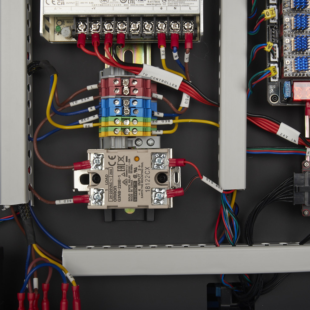
Step 00a.7 — The SSR is marked "earth the mounting rail" and this build does not
Step 7 of 12 · Chapter 00a — Mains safety: read before Chapter 09
Parts: none.
Do: Before Ch 09, settle who decides whether the SSR's EARTH THE MOUNTING RAIL marking must be honoured on this build. LDO's build does not run a PE conductor to the DIN rail.
Check
You can state what the marking asks for, what this build does, and who decides whether that is acceptable where you live.
What you're looking at
The solid-state relay on its bracket, with the wording on its body legible: 1 LOAD 2, 3 + INPUT 4 −, and EARTH THE MOUNTING RAIL. An SSR is a semiconductor switch with no moving contacts; here it switches mains to the bed heater.
The photo is from LDO's Rev C guide, so the relay in it is the 20 A G3NB-220B-1 and the bus behind it is DIN terminal blocks; your Rev D kit ships the 10 A G3NB-210B-1 and WAGO 221 blocks, and carries the same marking. 10.10 records the marking as you read it off the body. Understand the gap before you are standing in front of it:
- The SSR is an Omron G3NB-210B-1 — 24–220 VAC 10 A on the 1 / 2 LOAD pair, 5–24 VDC on the 3 + / 4 − INPUT pair (09.17). It bolts to a stamped metal bracket which clips to a DIN rail, and that rail bolts to a frame extrusion at 09.5.
- So the rail is bonded to the frame, and the frame is earthed at 10.16 — but through anodised aluminium and steel screws, incidentally. Ch 10.16 tells you to scrape the anodising under the frame PE washer precisely because anodising is an insulator. An incidental bond through two more anodised interfaces is not the same thing as a PE conductor, and it is not a compliance argument.
- Ch 10 states the consequence plainly: if your local rules require an earthed rail, that is a mains change and it belongs to whoever signs off your mains work — not to a decision you make at the bench.
Two more facts from Omron's own datasheet that change how you handle this part. The standard G3NB has no terminal cover — Omron's note is that "If you need a terminal cover, please use the G3NA-240B or similar product" — so four mains-carrying screw terminals sit exposed in your bay until Ch 11 closes it. And the relay's internal snubber leaks: "A leakage current flows through a snubber circuit in the G3NB even when there is no power input. Therefore, always turn OFF the power to the input or load and check that it is safe before replacing or wiring the G3NB."
Omron's caution for this relay
"Be sure to conduct wiring with the power supply turned OFF" and "Do not touch the G3NB's main circuit terminals immediately after the power is turned OFF." Ch 10 already sequences it that way: every mains connection is made with the cord in another room, and 10.73 measures 0 V for ten seconds first.
Source: Omron — Solid State Relays G3NB datasheet (J164-E1) · image: LDO SSR_Close_Up.jpg · Ch 10 Step 10.10 · Ch 09 Step 09.17