Step 00a.6 — Learn the protective-earth chain in this build¶
Step 6 of 12 · Chapter 00a — Mains safety: read before Chapter 09
Parts: none.
Do: Learn the five protective-earth branches in the table below, and where each is verified, before you meet them in Ch 09 and Ch 10.
Check
You can draw the five branches from memory and say where each is verified.
What you're looking at
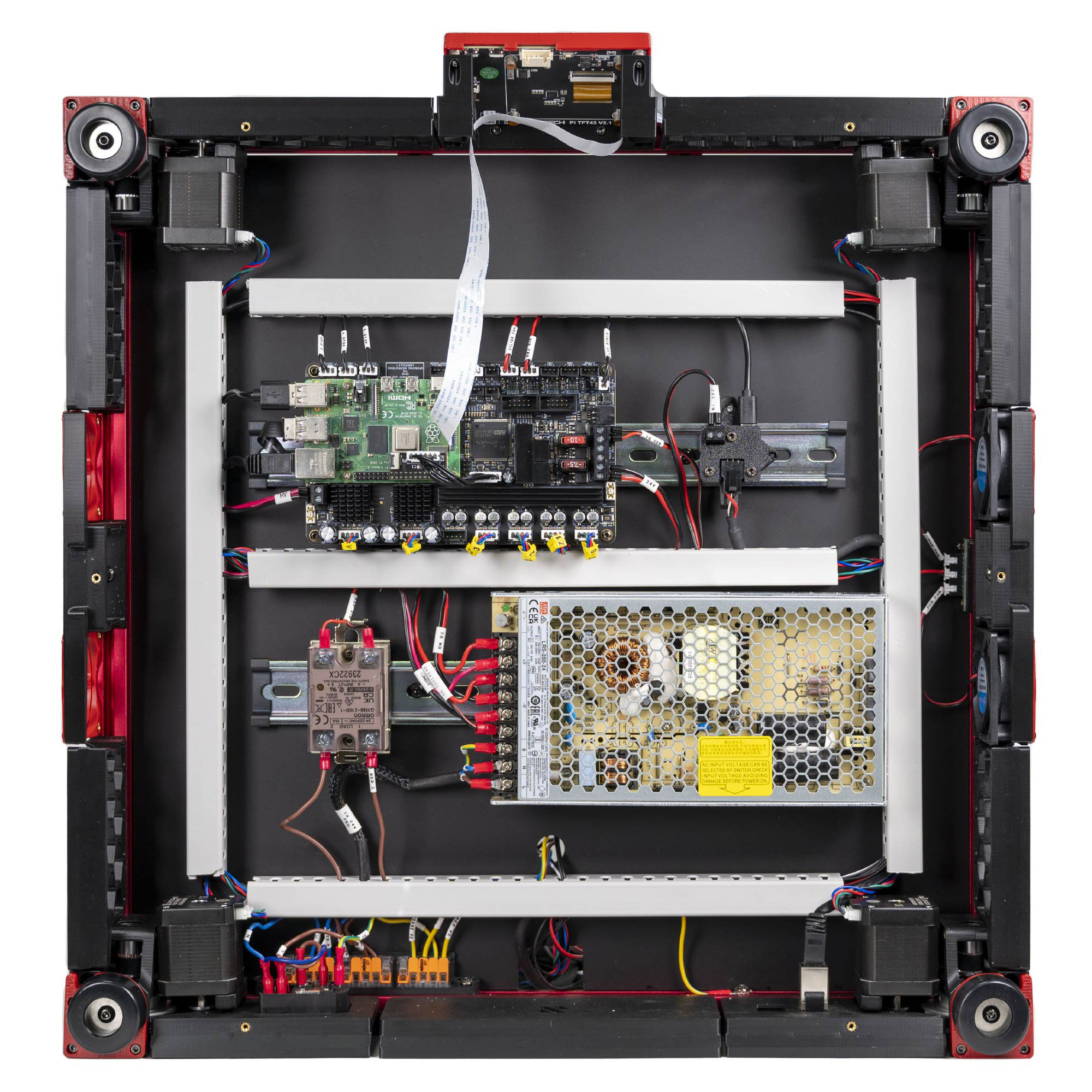
LDO's photo of the finished bay. Every branch of the protective earth chain is in this one frame: the inlet, the yellow/green WAGO block, the PSU's earth screw, the ring terminal on a frame extrusion, and the lead to the build plate.
The whole chain is proved in one sweep at 10.77: from the C14 earth pin, the PE WAGO and PSU ⏚ read < 1 Ω, the frame PE lug and the plate's M4×6 PE screw read < 1 Ω, a far frame corner < 2–3 Ω, and the extruder motor body a few Ω or less — while the bed heater's L and N, and the +24 V side of the rail, read OL. The rail's −V / GND side reads a few Ω on purpose — that is the ESD bond from 10.58, and 10.74 and 10.77 both expect it; do not go hunting a reversed ferrule for it.
Protective earth (PE) is the conductor that makes the machine safe to touch: if a live conductor ever reaches the frame, the bed or a motor can, PE gives that current a path with far less resistance than you, and the fault current trips the breaker or the RCD. The diagram lays out the whole mains path end to end alongside all five PE branches, and which pole the fuse and rocker switch each sit in. Voron's electrical page is explicit that this is not optional on an AC-bed machine — "If using an AC powered bed, be sure to ground the bed regardless of if the assembly manual specifies it or not", and "Grounding the frame is recommended." RepRap adds the constraint people get wrong: "Earth shall be connected to a valid earth, never on plumbing."
| Branch | Runs from → to | Made at |
|---|---|---|
| Supply | wall socket earth → C14 E pin, through the C13 cord. Never switched, never fused | 10.5 |
| Bus | C14 E → the yellow PE WAGO (one of three 5-way blocks) | 10.7, 10.8 |
| PSU | PE WAGO → the Meanwell's ⏚ terminal — the innermost of its three AC screws, next to −V. Order from the outer end is L, N, ⏚ (LRS-200 datasheet: 1 AC/L, 2 AC/N, 3 FG) | 10.9 |
| Frame | PE WAGO → the rear frame extrusion between the mains WAGO mount and the deck notch (layout v3; on LDO's layout, right of the notch), ring terminal sandwiched between two M5 locking washers on bare metal | 10.16 |
| Bed | build plate → PE WAGO, ring terminal on the plate's own M4×6 BHCS + serrated washer | 03.6, 10.12, 10.15 |
A sixth path is not protective earth but shares the same bus at the far end: the ESD ground from the extruder motor body to the toolboard, fitted at 10.58. It is why the extruder can appears in the earth-bonding table.
Caution
Rev D+ / LDO: the bed's PE screw is already fitted to the plate and is an M4×6 BHCS, not the M3×6 the official manual asks you to supply. Verify it is tight at Step 03.6; do not remove it and refit it. Its serrated washer is what bites through the surface to make the bond. src
Source: Voron docs — Electrical Wiring · RepRap — Safety · Mean Well LRS-200 spec sheet — terminal pin assignment · LDO wiring guide § Frame PE · image: LDO VS9_Final.jpg · Ch 10 Step 10.77